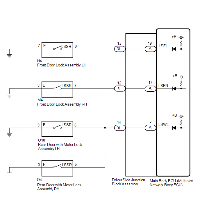
DESCRIPTION
The main body ECU (multiplex network body ECU) detects the condition of each
door unlock detection switch.
WIRING DIAGRAM
PROCEDURE
|
1.
|
READ VALUE USING TECHSTREAM
|
(a) Read the Data List according to the display on the Techstream.
Click here 
Main Body
|
Tester Display
|
Measurement Item / Range
|
Normal Condition
|
Diagnostic Note
|
|
FR Door Lock Pos
|
Front door RH unlock detection switch signal / LOCK or UNLOCK
|
LOCK: Front door RH locked
UNLOCK: Front door RH unlocked
|
-
|
|
FL Door Lock Pos
|
Front door LH unlock detection switch signal / LOCK or UNLOCK
|
LOCK: Front door LH locked
UNLOCK: Front door LH unlocked
|
-
|
|
RR-Door Lock Pos SW
|
Rear door unlock detection switch LH and RH signal / OFF or ON
|
OFF: LH and RH side rear door locked
ON: LH or RH side rear door unlocked
|
-
|
|
RL-Door Lock Pos SW
|
Rear door unlock detection switch LH and RH signal / OFF or ON
|
OFF: LH and RH side rear door locked
ON: LH or RH side rear door unlocked
|
-
|
OK:
Normal conditions listed above are displayed.
|
Result
|
Proceed to
|
|
OK
|
A
|
|
NG ("FL Door Lock Pos" is abnormal)
|
B
|
|
NG ("FR Door Lock Pos" is abnormal)
|
C
|
|
NG ("RR-Door Lock Pos SW" or "RL-Door Lock Pos SW" is abnormal)
|
D
|
| A |
 |
PROCEED TO NEXT SUSPECTED AREA SHOWN IN PROBLEM SYMPTOMS TABLE
|
| C |
|
GO TO STEP 5
|
| D |
|
GO TO STEP 8
|
| B |

|
|
|
2.
|
INSPECT FRONT DOOR LOCK ASSEMBLY LH
|
(a) Remove the front motor lock assembly LH.
for Double Cab:
for CrewMax:
(b) Inspect the front motor lock assembly LH.
for Double Cab:
for CrewMax:
| NG |
|
REPLACE FRONT DOOR LOCK ASSEMBLY LH
|
| OK |
|
|
|
|
3.
|
CHECK HARNESS AND CONNECTOR (FRONT DOOR LOCK ASSEMBLY LH - DRIVER SIDE
JUNCTION BLOCK ASSEMBLY)
|
(a) Disconnect the N4 front motor lock assembly LH connector.
(b) Disconnect the 3I driver side junction block assembly connector.
(c) Measure the resistance according to the value(s) in the table below.
Standard Resistance:
|
Tester Connection
|
Condition
|
Specified Condition
|
|
N4-8 (LSSR) - 3I-13
|
Always
|
Below 1 Ω
|
|
N4-8 (LSSR) or 3I-13 - Body ground
|
Always
|
10 kΩ or higher
|
|
N4-7 (E) - Body ground
|
Always
|
Below 1 Ω
|
| NG |
|
REPAIR OR REPLACE HARNESS OR CONNECTOR
|
| OK |
|
|
|
|
4.
|
CHECK DRIVER SIDE JUNCTION BLOCK ASSEMBLY
|
|
(a) Remove the driver side junction block assembly.
Click here
|
|
|
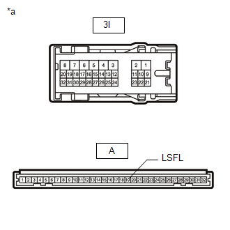
*a
|
Component without harness connected
(Driver Side Junction Block Assembly)
|
|
|
(b) Remove the main body ECU (multiplex network body ECU) from the driver side
junction block assembly.
Click here
(c) Measure the resistance according to the value(s) in the table below.
Standard Resistance:
|
Tester Connection
|
Condition
|
Specified Condition
|
|
3I-13 - A-19 (LSFL)
|
Always
|
Below 1 Ω
|
| OK |
|
REPLACE MAIN BODY ECU (MULTIPLEX NETWORK BODY ECU)
|
| NG |
|
REPLACE DRIVER SIDE JUNCTION BLOCK ASSEMBLY
|
|
5.
|
INSPECT FRONT DOOR LOCK ASSEMBLY RH
|
(a) Remove the front motor lock assembly RH.
for Double Cab:
for CrewMax:
(b) Inspect the front motor lock assembly RH.
for Double Cab:
for CrewMax:
| NG |
|
REPLACE FRONT DOOR LOCK ASSEMBLY RH
|
| OK |
|
|
|
|
6.
|
CHECK HARNESS AND CONNECTOR (FRONT DOOR LOCK ASSEMBLY RH - DRIVER SIDE
JUNCTION BLOCK ASSEMBLY)
|
(a) Disconnect the M4 front motor lock assembly RH connector.
(b) Disconnect the 3I driver side junction block assembly connector.
(c) Measure the resistance according to the value(s) in the table below.
Standard Resistance:
|
Tester Connection
|
Condition
|
Specified Condition
|
|
M4-7 (LSSR) - 3I-12
|
Always
|
Below 1 Ω
|
|
M4-7 (LSSR) or 3I-12 - Body ground
|
Always
|
10 kΩ or higher
|
|
M4-8 (E) - Body ground
|
Always
|
Below 1 Ω
|
| NG |
|
REPAIR OR REPLACE HARNESS OR CONNECTOR
|
| OK |
|
|
|
|
7.
|
CHECK DRIVER SIDE JUNCTION BLOCK ASSEMBLY
|
|
(a) Remove the driver side junction block assembly.
Click here
|

|
|
*a
|
Component without harness connected
(Driver Side Junction Block Assembly)
|
|
|
(b) Remove the main body ECU (multiplex network body ECU) from the driver side
junction block assembly.
Click here
(c) Measure the resistance according to the value(s) in the table below.
Standard Resistance:
|
Tester Connection
|
Condition
|
Specified Condition
|
|
3I-12 - A-17 (LSFR)
|
Always
|
Below 1 Ω
|
| OK |
|
REPLACE MAIN BODY ECU (MULTIPLEX NETWORK BODY ECU)
|
| NG |
|
REPLACE DRIVER SIDE JUNCTION BLOCK ASSEMBLY
|
|
8.
|
INSPECT REAR DOOR WITH MOTOR LOCK ASSEMBLY LH
|
(a) Remove the rear door with motor lock assembly LH.
for Double Cab:
for CrewMax:
(b) Inspect the rear door with motor lock assembly RH.
for Double Cab:
for CrewMax:
| NG |
|
REPLACE REAR DOOR WITH MOTOR LOCK ASSEMBLY LH
|
| OK |
|
|
|
|
9.
|
INSPECT REAR DOOR WITH MOTOR LOCK ASSEMBLY RH
|
(a) Remove the rear door with motor lock assembly RH.
for Double Cab:
for CrewMax:
(b) Inspect the rear door with motor lock assembly RH.
for Double Cab:
for CrewMax:
| NG |
|
REPLACE REAR DOOR WITH MOTOR LOCK ASSEMBLY RH
|
| OK |
|
|
|
|
10.
|
CHECK HARNESS AND CONNECTOR (REAR DOOR WITH MOTOR LOCK ASSEMBLY LH -
DRIVER SIDE JUNCTION BLOCK ASSEMBLY)
|
(a) Disconnect the O10 rear door with motor lock assembly LH connector.
(b) Disconnect the 3I driver side junction block assembly connector.
(c) Measure the resistance according to the value(s) in the table below.
Standard Resistance:
|
Tester Connection
|
Condition
|
Specified Condition
|
|
O10-6 (LSSR) - 3I-14
|
Always
|
Below 1 Ω
|
|
O10-6 (LSSR) or 3I-14 - Body ground
|
Always
|
10 kΩ or higher
|
|
O10-9 (E) - Body ground
|
Always
|
Below 1 Ω
|
| NG |
|
REPAIR OR REPLACE HARNESS OR CONNECTOR
|
| OK |
|
|
|
|
11.
|
CHECK HARNESS AND CONNECTOR (REAR DOOR WITH MOTOR LOCK ASSEMBLY RH -
DRIVER SIDE JUNCTION BLOCK ASSEMBLY)
|
(a) Disconnect the O4 rear door with motor lock assembly RH connector.
(b) Disconnect the 3I driver side junction block assembly connector.
(c) Measure the resistance according to the value(s) in the table below.
Standard Resistance:
|
Tester Connection
|
Condition
|
Specified Condition
|
|
O4-6 (LSSR) - 3I-14
|
Always
|
Below 1 Ω
|
|
O4-6 (LSSR) or 3I-14 - Body ground
|
Always
|
10 kΩ or higher
|
|
O4-9 (E) - Body ground
|
Always
|
Below 1 Ω
|
| NG |
|
REPAIR OR REPLACE HARNESS OR CONNECTOR
|
| OK |
|
|
|
|
12.
|
CHECK DRIVER SIDE JUNCTION BLOCK ASSEMBLY
|
|
(a) Remove the driver side junction block assembly.
Click here
|
|
|
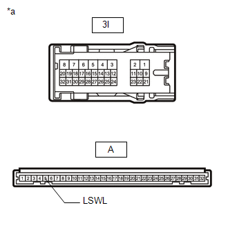
*a
|
Component without harness connected
(Driver Side Junction Block Assembly)
|
|
|
(b) Remove the main body ECU (multiplex network body ECU) from the driver side
junction block assembly.
Click here
(c) Measure the resistance according to the value(s) in the table below.
Standard Resistance:
|
Tester Connection
|
Condition
|
Specified Condition
|
|
3I-14 - A-5 (LSWL)
|
Always
|
Below 1 Ω
|
| OK |
|
REPLACE MAIN BODY ECU (MULTIPLEX NETWORK BODY ECU)
|
| NG |
|
REPLACE DRIVER SIDE JUNCTION BLOCK ASSEMBLY
|
| 

