Toyota Tundra Service Manual: Interior Light Circuit

DESCRIPTION

The main body ECU (multiplex network body ECU) controls the operation of the following lights:

  • Roof console box (front interior light)
  • No. 1 room light assembly (rear interior light)
  • Foot light bulb (w/ Foot Light)
  • Transponder key coil (w/ Ignition Key Cylinder Light)

WIRING DIAGRAM

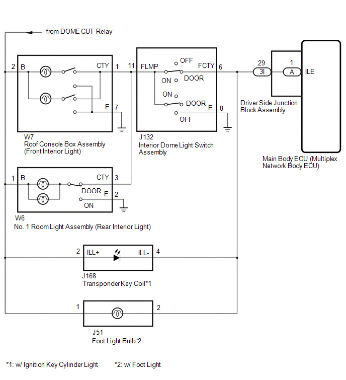
CAUTION / NOTICE / HINT

NOTICE:

Inspect the bulbs for circuits related to this system before performing the following procedure.

PROCEDURE

1.

PERFORM ACTIVE TEST USING TECHSTREAM

(a) Using the Techstream, perform the Active Test.

Click here

Main Body

Tester Display

Test Part

Control Range

Diagnostic Note

Illuminated Entry System

Illumination

OFF or ON

Perform the Active Test when DOOR switch in the interior dome light switch assembly, roof console box assembly (front interior light) and No. 1 room light assembly (rear interior light) turned on.

OK:

All of the interior lights turn on when ON is selected.

OK

PROCEED TO NEXT SUSPECTED AREA SHOWN IN PROBLEM SYMPTOMS TABLE

NG

2.

CHECK HARNESS AND CONNECTOR (DRIVER SIDE JUNCTION BLOCK ASSEMBLY - INTERIOR DOME LIGHT SWITCH ASSEMBLY)

  • *1: w/ Transponder Key Light
  • *2: w/ Foot Light

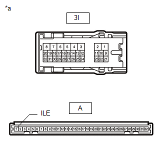
(a) Disconnect the 3I driver side junction block assembly connector.

(b) Disconnect the J132 interior dome light switch assembly connector.

(c) Disconnect the J168 transponder key coil connector.*1

(d) Disconnect the J51 foot light bulb connector.*2

(e) Measure the resistance according to the value(s) in the table below.

Standard Resistance:

Tester Connection

Condition

Specified Condition

3I-29 - J132-6 (FCTY)

Always

Below 1 Ω

NG

REPAIR OR REPLACE HARNESS OR CONNECTOR

OK

3.

CHECK DRIVER SIDE JUNCTION BLOCK ASSEMBLY

(a) Remove the driver side junction block assembly.

Click here

*a

Component without harness connected

(Driver Side Junction Block Assembly)

(b) Remove the main body ECU (multiplex network body ECU) from the driver side junction block assembly.

Click here

(c) Measure the resistance according to the value(s) in the table below.

Standard Resistance:

Tester Connection

Condition

Specified Condition

3I-29 - A-1 (ILE)

Always

Below 1 Ω

OK

REPLACE MAIN BODY ECU (MULTIPLEX NETWORK BODY ECU)

NG

REPLACE DRIVER SIDE JUNCTION BLOCK ASSEMBLY

    Interior Light Auto Cut Circuit

    Operation Check

    See More:

    Toyota Tundra Service Manual > Starter(for 2.0 Kw Type): Inspection
    INSPECTION PROCEDURE 1. INSPECT STARTER ASSEMBLY CAUTION: As a large electric current passes through the cable during this inspection, a thick cable must be used. Otherwise, the cable may become hot and cause injury. NOTICE: These tests must be performed within 3 to 5 seconds to avoid burning out th ...

    Toyota Tundra Owners Manual

    Toyota Tundra Service Manual

    © 2024 Copyright www.ttundra.com
    0.0236