Components COMPONENTS ILLUSTRATION 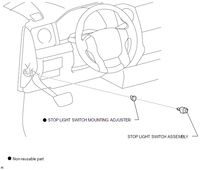
Inspection INSPECTION PROCEDURE 1. INSPECT STOP LIGHT SWITCH ASSEMBLY 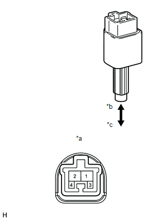
(a) Measure the resistance according to the value(s) in the table below. Standard Resistance:
If the result is not as specified, replace the stop light switch assembly. Text in Illustration
Installation INSTALLATION PROCEDURE 1. INSTALL STOP LIGHT SWITCH MOUNTING ADJUSTER (a) Attach the 2 claws to install a new stop light switch mounting adjuster. 2. INSTALL STOP LIGHT SWITCH ASSEMBLY 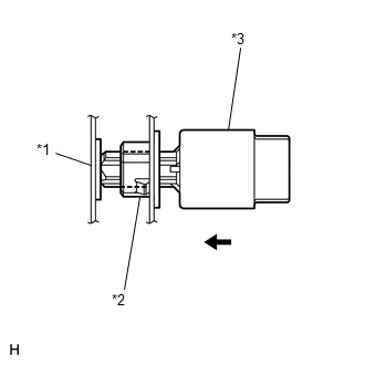
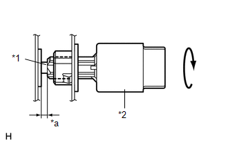
(a) Install the stop light switch assembly to the stop light switch mounting adjuster until the switch body slightly touches the brake pedal. NOTICE: Do not depress the brake pedal. Text in Illustration
(c) Check the stop light switch assembly clearance. Stop light switch assembly clearance: 1.5 to 2.5 mm (0.0590 to 0.0984 in.) (d) Connect the connector to the stop light switch assembly. (e) Install the stop light switch cover. Removal REMOVAL PROCEDURE 1. REMOVE STOP LIGHT SWITCH ASSEMBLY 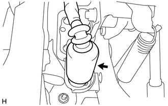
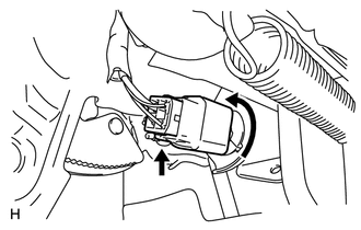
(a) Partially remove the stop light switch cover.
(c) Turn the stop light switch assembly counterclockwise and remove the stop light switch assembly. 2. REMOVE STOP LIGHT SWITCH MOUNTING ADJUSTER 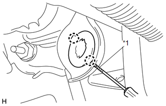
(a) Using a screwdriver, detach the 2 claws and remove the stop light switch mounting adjuster. HINT: Tape the screwdriver tip before use. Text in Illustration
|
Toyota Tundra Service Manual > Axle: Rear Axle Hub Bolt
ComponentsCOMPONENTS ILLUSTRATION ReplacementREPLACEMENT CAUTION / NOTICE / HINT HINT: Use the same procedures for the LH side and RH side. The procedures listed below are for the LH side. PROCEDURE 1. REMOVE REAR WHEEL LH 2. DISCONNECT REAR DISC BRAKE CYLINDER ASSEMBLY LH 3. REMOVE REAR DISC LH 4. ...