Toyota Tundra Service Manual: Power Mirrors do not Return to Memorized Position

Toyota Tundra Service Manual / Vehicle Interior / Mirror / Power Mirror Control System(w/ Memory) / Power Mirrors do not Return to Memorized Position

DESCRIPTION

If any of the M1 or M2 seat memory switch is pressed, the outer mirror control ECU assembly LH detects the switch operation and sends the seat memory switch signal to the main body ECU (multiplex network body ECU) via CAN communication. The main body ECU (multiplex network body ECU) sends the reproduction signal to each outer mirror control ECU assembly via CAN communication. When receiving the reproduction signal, each outer mirror control ECU assembly operates the vertical and horizontal mirror motors, which are built into the outer rear view mirror assembly, to adjust the mirror surface to the stored position.

WIRING DIAGRAM

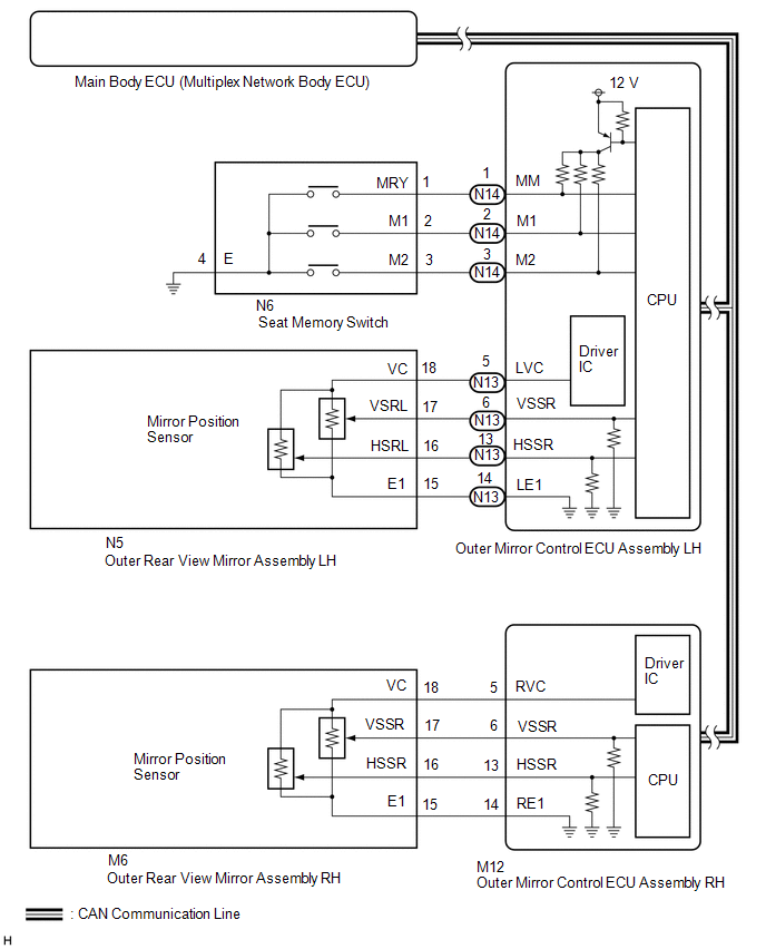
CAUTION / NOTICE / HINT

NOTICE:

The power mirror control system uses the CAN communication system. First, confirm that there is no malfunction in the CAN communication system. Refer to the How to Proceed with Troubleshooting procedure.

Click here

PROCEDURE

1.

CHECK SEAT MEMORY SWITCH FUNCTION

(a) When any seat memory switch (M1 or M2) is pressed, check that the driver seat moves to the memorized position.

Click here

OK:

Driver seat moves to the memorized position.

NG

GO TO FRONT POWER SEAT CONTROL SYSTEM (HOW TO PROCEED WITH TROUBLESHOOTING)

OK

2.

CHECK ELECTRICAL REMOTE CONTROL MIRROR FUNCTION

(a) Check the electrical remote control mirror function.

Click here

OK:

Electrical remote control mirror function is normal.

NG

GO TO OTHER DIAGNOSTIC PROCEDURE (HOW TO PROCEED WITH TROUBLESHOOTING)

OK

3.

READ VALUE USING TECHSTREAM (MIRROR MEMORY)

(a) Using the Techstream, read the Data List.

Click here

(1) for LH Side:

Mirror L

Tester Display

Measurement Item/Range

Normal Condition

Diagnostic Note

Mirror Memory No.1

Mirror position memorized in memory switch M1 / OFF or ON

OFF: Not memorized

ON: Memorized

-

Mirror Memory No.2

Mirror position memorized in memory switch M2 / OFF or ON

OFF: Not memorized

ON: Memorized

-

(2) for RH Side:

Mirror R

Tester Display

Measurement Item/Range

Normal Condition

Diagnostic Note

Mirror Memory No.1

Mirror position memorized in memory switch M1 / OFF or ON

OFF: Not memorized

ON: Memorized

-

Mirror Memory No.2

Mirror position memorized in memory switch M2 / OFF or ON

OFF: Not memorized

ON: Memorized

-

OK:

ON (Memorized) appears on the screen.

NG

GO TO OTHER DIAGNOSTIC PROCEDURE (Power Mirror Surface Position is not Memorized)

OK

4.

CHECK MEMORY AND REACTIVATION FUNCTION

(a) Check the memory and reactivation function.

Click here

Result

Proceed to

Memory and reactivation functions on both mirrors are not normal

A

Memory and reactivation function on driver door mirror is not normal

B

Memory and reactivation function on front passenger door mirror is not normal

C

A

REPLACE MAIN BODY ECU (MULTIPLEX NETWORK BODY ECU)

C

GO TO STEP 8

B

5.

CHECK HARNESS AND CONNECTOR (OUTER MIRROR CONTROL ECU ASSEMBLY LH - OUTER REAR VIEW MIRROR ASSEMBLY LH)

(a) Disconnect the N13 outer mirror control ECU assembly LH connector.

(b) Disconnect the N5 outer rear view mirror assembly LH connector.

(c) Measure the resistance according to the value(s) in the table below.

Standard Resistance:

Tester Connection

Condition

Specified Condition

N13-5 (LVC) - N5-18 (VC)

Always

Below 1 Ω

N13-6 (VSSR) - N5-17 (VSRL)

Always

Below 1 Ω

N13-13 (HSSR) - N5-16 (HSRL)

Always

Below 1 Ω

N13-14 (LE1) - N5-15 (E1)

Always

Below 1 Ω

N13-5 (LVC) or N5-18 (VC) - Body ground

Always

10 kΩ or higher

N13-6 (VSSR) or N5-17 (VSRL) - Body ground

Always

10 kΩ or higher

N13-13 (HSSR) or N5-16 (HSRL) - Body ground

Always

10 kΩ or higher

N13-14 (LE1) or N5-15 (E1) - Body ground

Always

10 kΩ or higher

NG

REPAIR OR REPLACE HARNESS OR CONNECTOR

OK

6.

REPLACE OUTER REAR VIEW MIRROR ASSEMBLY LH

(a) Temporarily replace the outer rear view mirror assembly LH with a new or known good one.

Click here

NEXT

7.

CHECK MEMORY AND REACTIVATION FUNCTION

(a) Check the memory and reactivation function.

Click here

OK

END (OUTER REAR VIEW MIRROR ASSEMBLY LH WAS DEFECTIVE)

NG

REPLACE OUTER MIRROR CONTROL ECU ASSEMBLY LH

8.

CHECK HARNESS AND CONNECTOR (OUTER MIRROR CONTROL ECU ASSEMBLY RH - OUTER REAR VIEW MIRROR ASSEMBLY RH)

(a) Disconnect the M12 outer mirror control ECU assembly RH connector.

(b) Disconnect the M6 outer rear view mirror assembly RH connector.

(c) Measure the resistance according to the value(s) in the table below.

Standard Resistance:

Tester Connection

Condition

Specified Condition

M12-5 (RVC) - M6-18 (VC)

Always

Below 1 Ω

M12-6 (VSSR) - M6-17 (VSSR)

Always

Below 1 Ω

M12-13 (HSSR) - M6-16 (HSSR)

Always

Below 1 Ω

M12-14 (RE1) - M6-15 (E1)

Always

Below 1 Ω

M12-5 (RVC) or M6-18 (VC) - Body ground

Always

10 kΩ or higher

M12-6 (VSSR) or M6-17 (VSSR) - Body ground

Always

10 kΩ or higher

M12-13 (HSSR) or M6-16 (HSSR) - Body ground

Always

10 kΩ or higher

M12-14 (RE1) or M6-15 (E1) - Body ground

Always

10 kΩ or higher

NG

REPAIR OR REPLACE HARNESS OR CONNECTOR

OK

9.

REPLACE OUTER REAR VIEW MIRROR ASSEMBLY RH

(a) Temporarily replace the outer rear view mirror assembly RH with a new or known good one.

Click here

NEXT

10.

CHECK MEMORY AND REACTIVATION FUNCTION

(a) Check the memory and reactivation function.

Click here

OK

END (OUTER REAR VIEW MIRROR ASSEMBLY RH WAS DEFECTIVE)

NG

REPLACE OUTER MIRROR CONTROL ECU ASSEMBLY RH

    Power Mirror Surface Position is not Memorized

    Power Retractable Mirrors do not Operate with Power Retract Mirror Switch

    See More:

    Toyota Tundra Service Manual > Lighting System: Hazard Warning Switch Circuit
    DESCRIPTION The combination meter assembly receives the air conditioning control assembly (hazard warning signal switch) ON signal and controls the operation of the hazard warning lights. WIRING DIAGRAM CAUTION / NOTICE / HINT NOTICE: When replacing the combination meter assembly, always replace it ...

    Toyota Tundra Owners Manual

    Toyota Tundra Service Manual

    © 2024 Copyright www.ttundra.com
    0.0376