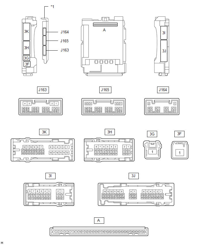
1. CHECK OUTER MIRROR CONTROL ECU ASSEMBLY LH
(a) Disconnect the N14 outer mirror control ECU assembly LH connector.
(b) Measure the voltage and resistance according to the value(s) in the table
below.
(c) Reconnect the N14 outer mirror control ECU assembly LH connector.
(d) Measure the voltage according to the value(s) in the table below.
|
Tester Connection
|
Wiring Color
|
Terminal Description
|
Condition
|
Specified Condition
|
|
N13-3 (MR+) - Body ground
|
SB - Body ground
|
Mirror retract motor output (retracting)
|
- Ignition switch ACC
- Outer rear view mirror assembly LH being retracted
|
11 to 14 V
|
|
N13-11 (MR-) - Body ground
|
R - Body ground
|
Mirror retract motor output (returning)
|
- Ignition switch ACC
- Outer rear view mirror assembly LH stopped
|
Below 1 V
|
|
N13-1 (LMVR) - Body ground
|
G - Body ground
|
Mirror motor drive voltage
|
- Ignition switch ACC
- Mirror surface stopped
|
Below 1 V
|
- Ignition switch ACC
- Mirror surface moving downward or left
|
Below 1 V
|
- Ignition switch ACC
- Mirror surface moving upward
|
11 to 14 V
|
|
N13-9 (LMHR) - Body ground
|
B - Body ground
|
Mirror motor drive voltage
|
- Ignition switch ACC
- Mirror surface stopped
|
Below 1 V
|
- Ignition switch ACC
- Mirror surface moving upward or right
|
Below 1 V
|
- Ignition switch ACC
- Mirror surface moving left
|
11 to 14 V
|
|
N13-10 (LM+R) - Body ground
|
G - Body ground
|
Mirror motor drive voltage
|
- Ignition switch ACC
- Mirror surface stopped
|
Below 1 V
|
- Ignition switch ACC
- Mirror surface moving upward or left
|
Below 1 V
|
- Ignition switch ACC
- Mirror surface moving downward or right
|
11 to 14 V
|
|
N13-5 (LVC) - N13-14 (LE1)
|
G - SB
|
Mirror position sensor power supply
|
Ignition switch ON
|
4.5 to 5.5 V
|
|
Ignition switch off
|
Below 1 V
|
|
N13-6 (VSSR) - Body ground
|
L - Body ground
|
Vertical direction position sensor signal
|
- Ignition switch ACC
- Mirror surface moving upward or downward
|
Changes within range of 0 to 5 V
|
|
N13-13 (HSSR) - Body ground
|
W - Body ground
|
Horizontal direction position sensor signal
|
- Ignition switch ACC
- Mirror surface moving left or right
|
Changes within range of 0 to 5 V
|
|
N14-2 (M1) - N14-7 (GND)
|
P - W-B
|
Seat memory switch M1 signal
|
- Ignition switch ON
- Seat memory switch M1 off
|
11 to 14 V
|
- Ignition switch ON
- Seat memory switch M1 on
|
Below 1 V
|
|
N14-3 (M2) - N14-7 (GND)
|
BE - W-B
|
Seat memory switch M2 signal
|
- Ignition switch ON
- Seat memory switch M2 off
|
11 to 14 V
|
- Ignition switch ON
- Seat memory switch M2 on
|
Below 1 V
|
|
N14-1 (MM) - N14-7 (GND)
|
L - W-B
|
Seat memory switch SET signal
|
- Ignition switch ON
- Seat memory switch SET off
|
11 to 14 V
|
- Ignition switch ON
- Seat memory switch SET on
|
Below 1 V
|
2. CHECK OUTER MIRROR CONTROL ECU ASSEMBLY RH
(a) Disconnect the M13 outer mirror control ECU assembly RH connector.
(b) Measure the voltage and resistance according to the value(s) in the table
below.
(c) Reconnect the M13 outer mirror control ECU assembly RH connector.
(d) Measure the voltage according to the value(s) in the table below.
|
Tester Connection
|
Wiring Color
|
Terminal Description
|
Condition
|
Specified Condition
|
|
M12-3 (MR+) - Body ground
|
P - Body ground
|
Mirror retract motor output (retracting)
|
- Ignition switch ACC
- Outer rear view mirror assembly RH being retracted
|
11 to 14 V
|
- Ignition switch ACC
- Outer rear view mirror assembly RH stopped
|
Below 1 V
|
|
M12-11 (MR-) - Body ground
|
R - Body ground
|
Mirror retract motor output (returning)
|
- Ignition switch ACC
- Outer rear view mirror assembly LH retuning
|
11 to 14 V
|
- Ignition switch ACC
- Outer rear view mirror assembly LH stopped
|
Below 1 V
|
|
M12-1 (RMVR) - Body ground
|
L - Body ground
|
Mirror motor drive voltage
|
- Ignition switch ACC
- Mirror surface stopped
|
Below 1 V
|
- Ignition switch ACC
- Mirror surface moving downward or left
|
Below 1 V
|
- Ignition switch ACC
- Mirror surface moving upward
|
11 to 14 V
|
|
M12-9 (RMHR) - Body ground
|
B - Body ground
|
Mirror motor drive voltage
|
- Ignition switch ACC
- Mirror surface stopped
|
Below 1 V
|
- Ignition switch ACC
- Mirror surface moving upward or right
|
Below 1 V
|
- Ignition switch ACC
- Mirror surface moving left
|
11 to 14 V
|
|
M12-10 (RM+R) - Body ground
|
BE - Body ground
|
Mirror motor drive voltage
|
- Ignition switch ACC
- Mirror surface stopped
|
Below 1 V
|
- Ignition switch ACC
- Mirror surface moving upward or left
|
Below 1 V
|
- Ignition switch ACC
- Mirror surface moving downward or right
|
11 to 14 V
|
|
M12-5 (RVC) - M12-14 (RE1)
|
G - SB
|
Mirror position sensor power supply
|
Ignition switch ON
|
4.5 to 5.5 V
|
|
Ignition switch off
|
Below 1 V
|
|
M12-6 (VSSR) - Body ground
|
L - Body ground
|
Vertical direction position sensor signal
|
- Ignition switch ACC
- Mirror surface moving upward or downward
|
Changes within range of 0 to 5 V
|
|
M12-13 (HSSR) - Body ground
|
W - Body ground
|
Horizontal direction position sensor signal
|
- Ignition switch ACC
- Mirror surface moving left or right
|
Changes within range of 0 to 5 V
|
3. CHECK DRIVER SIDE JUNCTION BLOCK ASSEMBLY AND MAIN BODY ECU (MULTIPLEX NETWORK
BODY ECU)
(a) Remove the main body ECU (multiplex network body ECU) from the driver side
junction block assembly.
(b) Connect the driver side junction block assembly connectors.
(c) Measure the voltage and resistance according to the value(s) in the table
below.
(d) Install the main body ECU (multiplex network body ECU) to the driver side
junction block assembly.
(e) Measure the voltage according to the value(s) in the table below.
|
Terminal No.
(Symbol)
|
Wiring Color
|
Terminal Description
|
Condition
|
Specified Condition
|
|
J163-14 (RET) - 3I-3
|
V - BR
|
Mirror retract motor output (retracting)
|
- Ignition switch ACC
- Outer mirror switch assembly (mirror retract switch) on
|
Below 1 V
|
- Ignition switch ACC
- Outer mirror switch assembly (mirror retract switch) off
|
11 to 14 V
|
|
J164-4 (MIRB) - J164-6 (MIRE)
|
R - GR
|
Mirror control switch signal
|
- Ignition switch ACC
- Outer mirror switch assembly (mirror control switch) right
|
Below 2.7 V
|
- Ignition switch ACC
- Outer mirror switch assembly (mirror control switch) left
|
Below 4 V
|
- Ignition switch ACC
- Outer mirror switch assembly (mirror control switch) down
|
Below 3.5 V
|
- Ignition switch ACC
- Outer mirror switch assembly (mirror control switch) up
|
Below 1.7 V
|
- Ignition switch ACC
- Outer mirror switch assembly (mirror control switch) not pushed
|
11 to 14 V
|
|
J164-5 (MIRS) - J164-6 (MIRE)
|
L - GR
|
Mirror master switch signal
|
- Ignition switch ACC
- Outer mirror switch assembly (mirror master switch) L
|
11 to 14 V
|
- Ignition switch ACC
- Outer mirror switch assembly (mirror master switch) R
|
Below 2 V
|
- Ignition switch ACC
- Outer mirror switch assembly (mirror master switch) neutral
|
Below 1 V
|