Toyota Tundra Service Manual: Terminals Of Ecu

TERMINALS OF ECU

1. CHECK RADIO AND DISPLAY RECEIVER ASSEMBLY

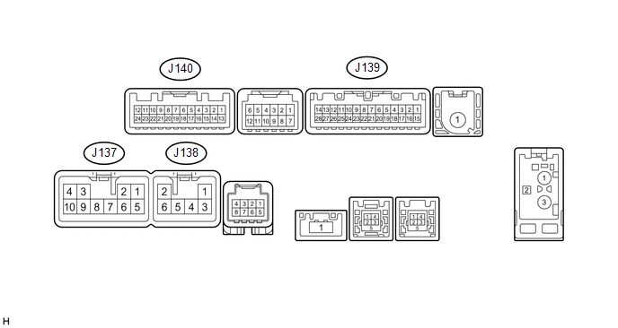
(a) Disconnect the J137 and J139 radio and display receiver assembly connectors.

(b) Measure the voltage and resistance according to the value(s) in the table below.

Terminal No. (Symbol)

Wiring Color

Terminal Description

Condition

Specification

J137-3 (ACC1) - J137-7 (GND1)

GR - BR

Power source (ACC)

Ignition switch off

Below 1 V

Ignition switch ACC

11 to 14 V

J137-4 (+B1) - J137-7 (GND1)

LA-SB - BR

Power source (+B)

Always

11 to 14 V

J137-7 (GND1) - Body ground

BR - Body ground

Ground

Always

Below 1 Ω

J139-1 (IG) - J137-7 (GND1)

BE - BR

Power source (IG)

Ignition switch off

Below 1 V

Ignition switch ON

11 to 14 V

(c) Reconnect the J137 and J139 radio and display receiver assembly connectors.

(d) Measure the voltage and waveform according to the value(s) in the table below.

Terminal No. (Symbol)

Wiring Color

Terminal Description

Condition

Specification

J139-2 (REV) - J137-7 (GND1)

Y - BR

Reverse signal

Ignition switch ON, shift lever in R

7.5 to 14 V

Ignition switch ON, shift lever not in R

Below 1 V

J140-11 (CA+) - J140-23 (CGND)

B - Shielded

Power source

Ignition switch ACC

5.5 to 7.05 V

J140-12 (V+) - J140-24 (V-)

R - W

Display signal

Ignition switch ON

Pulse generation (See waveform 1)

Ignition switch ON, screen blacked out by covering camera lens

Pulse generation (See waveform 2)

J140-23 (CGND) - Body ground

Shielded - Body ground

Shielded ground

Always

Below 1 Ω

(e) Using an oscilloscope, check the waveform.

*a

Waveform 1

*b

Waveform 2

*c

Synchronization Signal

*d

Video Waveform

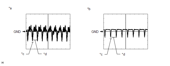
(1) Waveform 1

Measurement Condition

Item

Content

Terminal No. (Symbol)

J140-12 (V+) - J140-24 (V-)

Tool Setting

0.2 V/DIV., 50 μs/DIV.

Condition

Ignition switch ON

HINT:

The video waveform changes according to the image sent by the television camera assembly.

(2) Waveform 2

Measurement Condition

Item

Content

Terminal No. (Symbol)

J140-12 (V+) - J140-24 (V-)

Tool Setting

0.2 V/DIV., 50 μs/DIV.

Condition

Ignition switch ON, screen blacked out by covering camera lens

HINT:

The video waveform changes according to the image sent by the television camera assembly.

    System Diagram

    Television Camera

    See More:

    Toyota Tundra Service Manual > Front Bumper: Reassembly
    REASSEMBLY CAUTION / NOTICE / HINT HINT: A bolt without a torque specification is shown in the standard bolt chart. Click here PROCEDURE 1. INSTALL LOWER NO. 1 RADIATOR GRILLE (a) Attach the 17 claws to install the lower No. 1 radiator grille to the front valance panel. 2. INSTALL FRONT BUMPER EXTEN ...

    Toyota Tundra Owners Manual

    Toyota Tundra Service Manual

    © 2024 Copyright www.ttundra.com
    0.0251