REASSEMBLY PROCEDURE 1. INSTALL STARTER CENTER BEARING CLUTCH SUB-ASSEMBLY
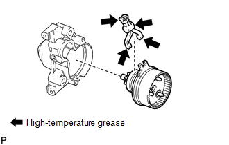
(b) Install the starter pinion drive lever and rubber seal to the starter center bearing clutch. (c) Install the starter center bearing clutch together with the starter pinion drive lever and rubber seal to the starter drive housing.
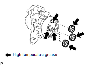
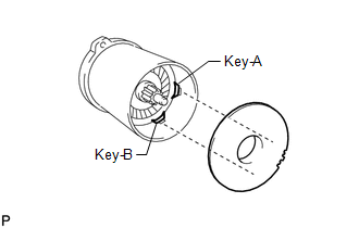
(e) Install the 3 planetary gears. 2. INSTALL STARTER ARMATURE ASSEMBLY (a) Install the starter armature to the starter yoke. NOTICE: The magnet of the starter yoke may attract the starter armature when the starter commutator end frame is installed causing the magnet to break. 3. INSTALL STARTER BRUSH HOLDER ASSEMBLY
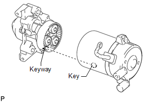
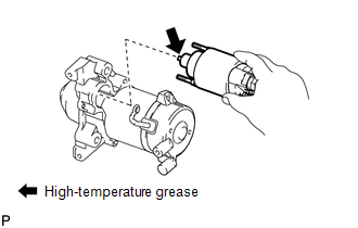
4. INSTALL STARTER YOKE ASSEMBLY
(b) Install the starter commutator end frame with the 2 screws. Torque: 1.5 N·m {15 kgf·cm, 13 in·lbf}
(d) Using a T25 "TORX" socket wrench, install the 2 bolts. Torque: 6.0 N·m {61 kgf·cm, 53 in·lbf} 5. INSTALL MAGNET STARTER SWITCH ASSEMBLY
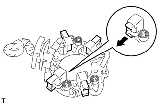
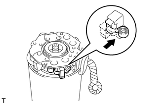
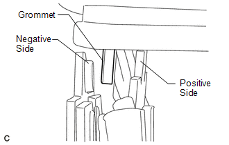
(b) Hang the plunger of the magnet starter switch onto the drive lever from the upper side. (c) Install the magnet starter switch with the 2 nuts. Torque: 7.5 N·m {76 kgf·cm, 66 in·lbf} (d) Connect the lead wire to the magnet starter switch with the nut. Torque: 10 N·m {102 kgf·cm, 7 ft·lbf} |
Toyota Tundra Service Manual > Inner Rear View Mirror: Installation
INSTALLATION PROCEDURE 1. INSTALL INNER REAR VIEW MIRROR ASSEMBLY (w/ EC Mirror) (a) Using a T20 "TORX" socket wrench, install the inner rear view mirror with the "TORX" screw. Torque: 1.2 N·m {12 kgf·cm, 11 in·lbf} "TORX" screw Connector (b) Connect the connector. 2 ...