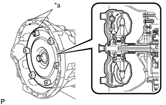
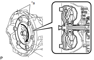
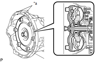
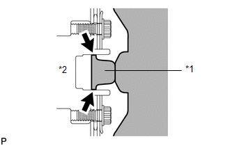
INSTALLATION PROCEDURE 1. INSTALL TORQUE CONVERTER CLUTCH ASSEMBLY 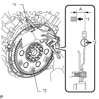 (a) Using a vernier caliper and straightedge, measure dimension "A" between the transmission fitting surface of the engine*1 and the torque converter fitting surface of the drive plate*2 (step 1).
2. INSTALL TRANSMISSION CONTROL CABLE BRACKET (a) Install the bracket with the 2 bolts. Torque: 12 N·m {122 kgf·cm, 9 ft·lbf} 3. INSTALL WIRE HARNESS CLAMP BRACKET 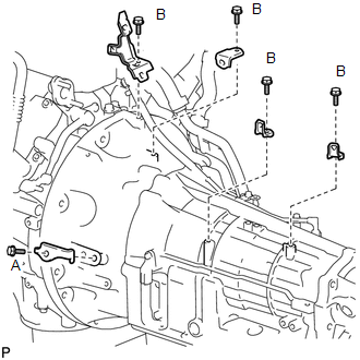 (a) Install the 5 wire harness clamp brackets with the 5 bolts. Torque: for bolt A : 60 N·m {612 kgf·cm, 44 ft·lbf} for bolt B : 8.0 N·m {82 kgf·cm, 71 in·lbf} 4. INSTALL AUTOMATIC TRANSMISSION ASSEMBLY
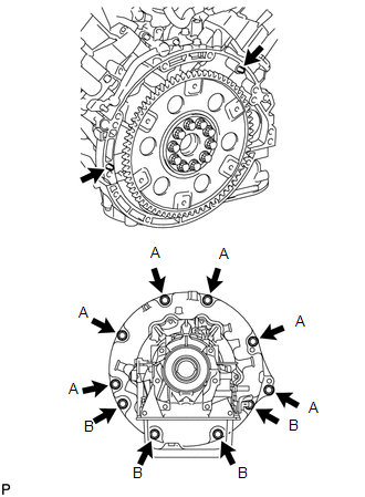
(c) Install the transmission with the 10 bolts. Torque: for 17 mm head bolt A : 71 N·m {724 kgf·cm, 52 ft·lbf} for 14 mm head bolt B : 37 N·m {377 kgf·cm, 27 ft·lbf} 5. INSTALL TRANSMISSION OIL COOLER ASSEMBLY
6. CONNECT WATER BY-PASS PIPE
7. CONNECT WIRE HARNESS AND CONNECTOR (a) Connect the park/neutral position switch connector, transmission wire connector and 2 speed sensor connectors. 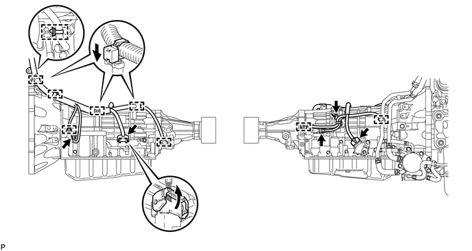 HINT: Push up the lever until the claw of the transmission wire connector makes a connection sound. (b) Connect the harness clamp with the bolt. Torque: 8.0 N·m {82 kgf·cm, 71 in·lbf} (c) Attach the 4 connector clamps and 5 harness clamps. (d) Tilt up the automatic transmission. (e) Connect the ground cable with the bolt. Torque: 8.4 N·m {85 kgf·cm, 74 in·lbf} 8. INSTALL REAR NO. 1 ENGINE MOUNTING INSULATOR (a) Install the rear engine mounting insulator to the transmission with the 4 bolts. Torque: 40 N·m {408 kgf·cm, 30 ft·lbf} 9. INSTALL NO. 3 FRAME CROSSMEMBER SUB-ASSEMBLY (a) Install the frame crossmember to the rear engine mounting insulator with the 4 bolts. Torque: 21 N·m {214 kgf·cm, 15 ft·lbf} (b) Install the frame crossmember with the 4 bolts, 4 washers and 4 nuts. Torque: 110 N·m {1122 kgf·cm, 81 ft·lbf} 10. INSTALL DRIVE PLATE AND TORQUE CONVERTER CLUTCH SETTING BOLT (a) Turn the crankshaft to gain access to the installation locations of the 6 torque converter clutch setting bolts and install each bolt while holding the crankshaft pulley bolt with a wrench. Torque: 53 N·m {535 kgf·cm, 39 ft·lbf} NOTICE: Install the black bolt first, and then the 5 silver bolts. (b) Install the flywheel housing side cover. 11. INSTALL STARTER ASSEMBLY (See page 12. CONNECT TRANSMISSION CONTROL CABLE ASSEMBLY 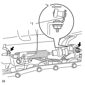 (a) Connect the control cable with a new clip and the nut. Torque: 13 N·m {133 kgf·cm, 10 ft·lbf} Text in Illustration
NOTICE: When connecting the cable to the transmission control shaft lever, make sure the L bracket of the cable faces the inside of the vehicle. 13. INSTALL FRONT EXHAUST PIPE ASSEMBLY (See page 14. INSTALL PROPELLER SHAFT ASSEMBLY (See page 15. CONNECT CABLE TO NEGATIVE BATTERY TERMINAL 16. ADD AUTOMATIC TRANSMISSION FLUID (See page
17. ADD ENGINE COOLANT 18. CHECK FOR ENGINE COOLANT LEAK 19. ADJUST SHIFT LEVER POSITION (for Column Shift Type) 20. ADJUST SHIFT LEVER POSITION (for Floor Shift Type) 21. INSPECT SHIFT LEVER POSITION (for Column Shift Type) 22. INSPECT SHIFT LEVER POSITION (for Floor Shift Type) 23. INSPECT FOR EXHAUST GAS LEAK 24. INSTALL NO. 1 ENGINE UNDER COVER 25. RESET MEMORY (See page |
Toyota Tundra Service Manual > Maintenance: Inside Vehicle
General MaintenanceGENERAL MAINTENANCE CAUTION / NOTICE / HINT Performing the following maintenance checks on the vehicle is the owner's responsibility. The owner may perform the maintenance or take the vehicle to a service center. Check the parts of the vehicle described below on a daily basis. In ...