DESCRIPTION This sensor
detects the rotation speed of the turbine which indicates the input
speed of the transmission. By comparing the input turbine speed signal
NT with the output speed sensor signal SP2, the ECM detects the shift
timing of the gears and appropriately controls the engine torque and
hydraulic pressure according to various conditions, and as a result, the
gears shift smoothly. |
DTC Code | DTC Detection Condition |
Trouble Area | | P0717 |
All conditions are met for 5 seconds or more (1-trip detection logic):
(a) Gear change is not performed. (b) Gear position is 4th, 5th or 6th.
(c) Transmission input shaft speed is less than 300 rpm. (d) Transmission output shaft speed is 1000 rpm or more.
(e) Park/neutral position switch NSW and R input signals are OFF.
(f) Shift solenoid valves and the park/neutral position switch are operating normally. |
- Open or short in speed sensor NT circuit
- Speed sensor NT
- ECM
- Automatic transmission (clutch, brake, gear, etc.)
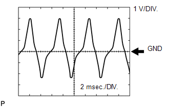
| Reference: Inspect using an oscilloscope.
Check the waveform of the ECM connector. Standard: |
Terminal No. (Symbol) | Tool Setting |
Condition | Specified Condition | |
D74-124 (NT+) - D74-123 (NT-) | 1 V/DIV., 2 msec./DIV. |
Engine is idling (Shift lever in P or N) |
Refer to illustration |
 MONITOR DESCRIPTION
This
DTC indicates that a pulse is not output from the speed sensor NT
(turbine (input) speed sensor) or is output only a little. The NT
terminal of the ECM detects the pulse signal from the speed sensor NT
(input RPM). The ECM outputs a gear shift signal by comparing the input
speed sensor NT signal with the output speed sensor SP2 signal. While
the vehicle is operating in 4th, 5th or 6th gear with the shift lever
in D, if the input shaft speed is less than 300 rpm*1 although the
output shaft speed is 1000 rpm or more*2, the ECM detects the trouble,
illuminates the MIL and stores the DTC.
HINT:
- *1: A pulse is not output or is irregularly output.
- *2: The vehicle speed is approximately 50 km/h (30 mph) or more.
MONITOR STRATEGY |
Related DTCs | P0717: Speed sensor (NT)/Verify pulse input | |
Required sensors/Components (Main) | Speed sensor (NT) | |
Required sensors/Components (Related) | Speed sensor (SP2) | |
Frequency of operation | Continuous | |
Duration | 5 seconds | | MIL operation |
Immediately | | Sequence of operation |
None | TYPICAL ENABLING CONDITIONS |
The monitor will run whenever the following DTCs are not present |
P0705 (Park/neutral position switch circuit) P0751, P0973, P0974 (Shift solenoid valve S1)
P0756, P0976, P0977 (Shift solenoid valve S2) P0761, P0979, P0980 (Shift solenoid valve S3)
P0766, P0982, P0983 (Shift solenoid valve S4) P0748 (Shift solenoid valve SL1 circuit)
P0776, P0778 (Shift solenoid valve SL2) | |
Shift change | After shift change is completed and before starting next shift change operation | |
ECM selected gear | 4th, 5th or 6th | |
Output shaft rpm | 1000 rpm or more | |
NSW switch | OFF | |
R switch | OFF | |
Engine | Running | |
Battery voltage | 8 V or more | |
Ignition switch | ON | |
Starter | OFF | TYPICAL MALFUNCTION THRESHOLDS |
Speed sensor signal rpm | Less than 300 rpm | COMPONENT OPERATING RANGE |
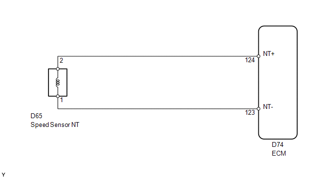
Speed sensor signal rpm | 300 rpm or more | WIRING DIAGRAM
 CAUTION / NOTICE / HINT
NOTICE: Perform the universal trip to clear permanent DTCs (See page
 ). ). 1. DATA LIST HINT: Using
the Techstream to read the Data List allows the values or states of
switches, sensors, actuators and other items to be read without removing
any parts. This non-intrusive inspection can be very useful because
intermittent conditions or signals may be discovered before parts or
wiring is disturbed. Reading the Data List information early in
troubleshooting is one way to save diagnostic time. NOTICE: In
the table below, the values listed under "Normal Condition" are
reference values. Do not depend solely on these reference values when
deciding whether a part is faulty or not. (a) Warm up the engine. (b) Turn the ignition switch off.
(c) Connect the Techstream to the DLC3. (d) Turn the ignition switch to ON.
(e) Turn the Techstream on. (f) Enter the following menus: Powertrain / Engine and ECT / Data List.
(g) According to the display on the Techstream, read the Data List. Engine and ECT |
Tester Display | Measurement Item/Range |
Normal Condition | Diagnostic Note | |
SPD (NT) | Input shaft speed/ Min.: 0 rpm
Max.: 12750 rpm |
- Lock-up ON (after warming up engine): Input turbine speed (NT) is equal to engine speed
- Lock-up OFF (idling with shift lever in N): Input turbine speed (NT) is nearly equal to engine speed
| Data is displayed in increments of 50 rpm. |
HINT:
- SPD (NT) is always 0 while driving:
Open or short in the sensor or circuit.
- SPD (NT) is always more than 0 and less than 300 rpm while driving the vehicle at 50 km/h (30 mph) or more:
Sensor trouble, improper installation, or intermittent connection trouble of the circuit.
PROCEDURE |
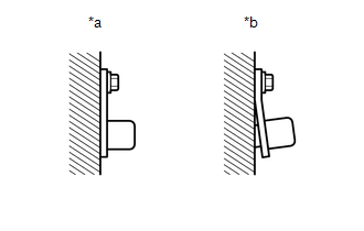
1. | INSPECT SPEED SENSOR NT INSTALLATION |
| (a) Check the speed sensor NT installation. OK: The installation bolt is tightened properly and there is no clearance between the sensor and transmission case. Text in Illustration |
|
| NG |
 | SECURELY INSTALL OR REPLACE SPEED SENSOR NT |
|
OK |
 | |
| 2. |
INSPECT SPEED SENSOR NT |
| (a) Disconnect the D65 speed sensor connector. | |
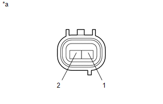
(b) Measure the resistance according to the value(s) in the table below.
Standard Resistance: |
Tester Connection | Condition |
Specified Condition | |
1 - 2 | 20°C (68°F) |
560 to 680 Ω | Text in Illustration |
*a | Component without harness connected
(Speed Sensor NT) |
| NG |
| REPLACE SPEED SENSOR NT |
|
OK | |
| |
| 3. |
CHECK HARNESS AND CONNECTOR (SPEED SENSOR NT - ECM) |
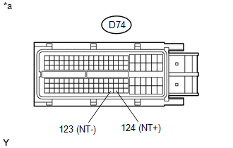
| (a) Disconnect the D74 ECM connector. | |
(b) Measure the resistance according to the value(s) in the table below.
Standard Resistance: |
Tester Connection | Condition |
Specified Condition | | D74-124 (NT+) - D74-123 (NT-) |
20°C (68°F) | 560 to 680 Ω | |
D74-124 (NT+) - Body ground |
Always | 10 kΩ or higher | |
D74-123 (NT-) - Body ground |
Always | 10 kΩ or higher | Text in Illustration |
*a | Front view of wire harness connector
(to ECM) |
| OK |
| REPLACE ECM |
| NG |
| REPAIR OR REPLACE HARNESS OR CONNECTOR | |