INSPECTION PROCEDURE 1. INSPECT AUTOMATIC TRANSMISSION OIL PAN SUB-ASSEMBLY  (a) Remove the magnets, and use them to collect steel particles. (b) Carefully look at the foreign matter and particles in the pan and on the magnets to anticipate the type of wear you will find in the transmission.
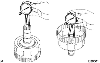
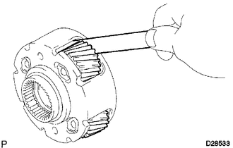
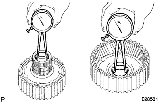
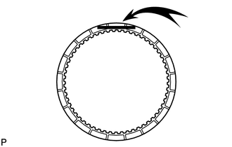
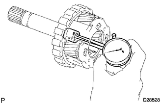
2. INSPECT NO. 2 1-WAY CLUTCH ASSEMBLY 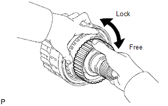 (a) Hold the reverse clutch hub and turn the 1-way clutch assembly. (b) Check that the 1-way clutch turns freely clockwise and locks when turned counterclockwise. If there is a problem with the 1- way clutch, replace the No. 2 1-way clutch assembly. 3. INSPECT REAR CLUTCH DISC 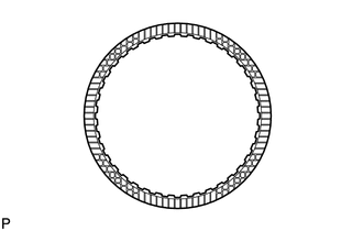 (a) Replace all discs if one of the following problems is present: 1) a disc, plate or flange is worn or burnt, 2) the lining of a disc is peeled off or discolored, or 3) the grooves or printed numbers have even a little bit of damage. NOTICE: Before assembling new discs, soak them in ATF for at least 15 minutes. 4. INSPECT REVERSE CLUTCH HUB SUB-ASSEMBLY 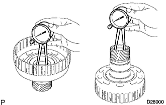 (a) Using a dial indicator, measure the inside diameter of the reverse clutch hub bush. Standard inside diameter: 35.812 to 35.837 mm (1.410 to 1.411 in.) Maximum inside diameter: 35.887 mm (1.413 in.)
5. INSPECT FORWARD CLUTCH HUB SUB-ASSEMBLY
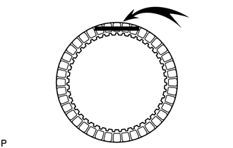
6. INSPECT UNDERDRIVE 1-WAY CLUTCH ASSEMBLY 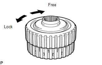 (a) Hold the coast clutch hub and turn the 1-way clutch assembly. Check that the 1-way clutch turns freely clockwise and locks when turned counterclockwise. If there is a problem with the 1-way clutch, replace the underdrive 1-way clutch assembly. 7. INSPECT FORWARD MULTIPLE DISC CLUTCH DISC 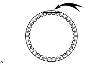 (a) Replace all discs if one of the following problems is present: 1) a disc, plate or flange is worn or burnt, 2) the lining of a disc is peeled off or discolored, or 3) the grooves or printed numbers have even a little bit of damage. NOTICE: Before assembling new discs, soak them in ATF for at least 15 minutes. 8. INSPECT COAST CLUTCH DISC 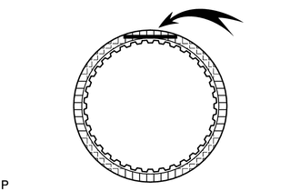
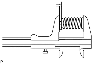
(a) Replace all discs if one of the following problems is present: 1) a disc, plate or flange is worn or burnt, 2) the lining of a disc is peeled off or discolored, or 3) the grooves or printed numbers have even a little bit of damage. NOTICE: Before assembling new discs, soak them in ATF for at least 15 minutes. 9. INSPECT FORWARD CLUTCH RETURN SPRING SUB-ASSEMBLY 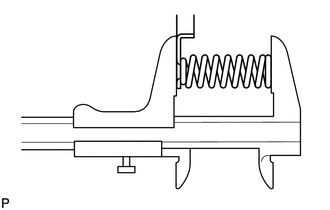 (a) Using a vernier caliper, measure the free length of the spring together with the spring seat. Standard free length: 26.74 mm (1.05 in.) If the free length is less than the standard, replace the forward clutch return spring sub-assembly. 10. INSPECT DIRECT CLUTCH DISC 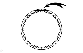
(a) Replace all discs if one of the following problems is present: 1) a disc, plate or flange is worn or burnt, 2) the lining of a disc is peeled off or discolored, or 3) the grooves or printed numbers have even a little bit of damage. NOTICE: Before assembling new discs, soak them in ATF for at least 15 minutes. 11. INSPECT REVERSE CLUTCH RETURN SPRING SUB-ASSEMBLY 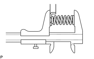 (a) Using a vernier caliper, measure the free length of the spring together with the spring seat. Standard free length: 21.04 mm (0.828 in.) If the free length is less than the standard, replace the reverse clutch return spring sub-assembly. 12. INSPECT DIRECT CLUTCH RETURN SPRING SUB-ASSEMBLY 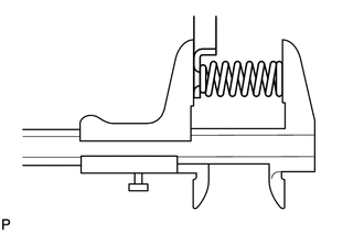 (a) Using a vernier caliper, measure the free length of the spring together with the spring seat. Standard free length: 19.51 mm (0.768 in.) If the free length is less than the standard, replace the direct clutch return spring sub-assembly. 13. INSPECT NO. 3 BRAKE DISC 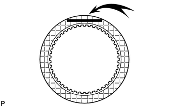
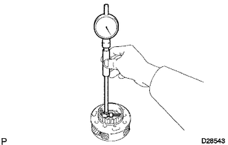
(a) Replace all discs if one of the following problems is present: 1) a disc, plate or flange is worn or burnt, 2) the lining of a disc is peeled off or discolored, or 3) the grooves or printed numbers have even a little bit of damage. NOTICE: Before assembling new discs, soak them in ATF for at least 15 minutes. 14. INSPECT NO. 3 BRAKE PISTON RETURN SPRING SUB-ASSEMBLY 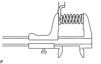 (a) Using a vernier caliper, measure the free length of the spring together with the spring seat. Standard free length: 15.72 mm (0.619 in.) If the free length is less than the standard, replace the No. 3 brake piston return spring sub-assembly. 15. INSPECT FRONT PLANETARY GEAR ASSEMBLY 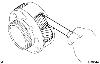 (a) Using a feeler gauge, measure the front planetary pinion gear thrust clearance. Standard clearance: 0.2 to 0.60 mm (0.00787 to 0.0236 in.) Maximum clearance: 0.65 mm (0.0256 in.)
16. INSPECT 1-WAY CLUTCH ASSEMBLY 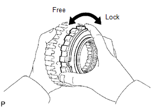 (a) Install the 1-way clutch to the 1-way clutch inner race. (b) Hold the 1-way clutch inner race and turn the 1-way clutch assembly. Check that the 1-way clutch turns freely counterclockwise and locks when turned clockwise. If there is a problem with the 1-way clutch, replace the 1-way clutch assembly. (c) Remove the 1-way clutch from the 1-way clutch inner race. 17. INSPECT NO. 1 BRAKE DISC  (a) Replace all discs if one of the following problems is present: 1) a disc, plate or flange is worn or burnt, 2) the lining of a disc is peeled off or discolored, or 3) the grooves or printed numbers have even a little bit of damage. NOTICE: Before assembling new discs, soak them in ATF for at least 15 minutes. 18. INSPECT BRAKE PISTON RETURN SPRING SUB-ASSEMBLY 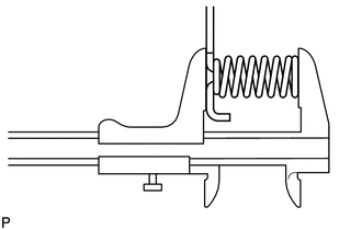 (a) Using a vernier caliper, measure the free length of the spring together with the spring seat. Standard free length: 17.05 mm (0.671 in.) If the free length is less than the standard, replace the brake piston return spring sub-assembly. 19. INSPECT NO. 2 BRAKE DISC
20. INSPECT NO. 2 BRAKE PISTON RETURN SPRING SUB-ASSEMBLY
21. INSPECT CENTER PLANETARY GEAR ASSEMBLY
22. INSPECT NO. 3 1-WAY CLUTCH ASSEMBLY 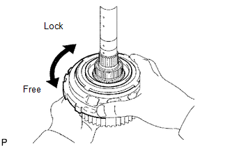 (a) Hold the rear planetary ring gear flange and turn the 1-way clutch. Check that the 1-way clutch turns freely counterclockwise and locks when turned clockwise. If there is a problem with the 1-way clutch, replace the No. 3 1-way clutch assembly. 23. INSPECT REAR PLANETARY RING GEAR FLANGE SUB-ASSEMBLY
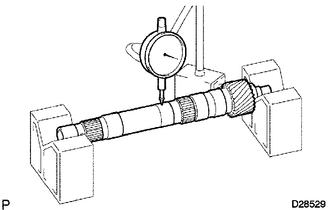
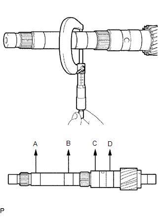
24. INSPECT INTERMEDIATE SHAFT
25. INSPECT NO. 4 BRAKE DISC
26. INSPECT REAR PLANETARY GEAR ASSEMBLY 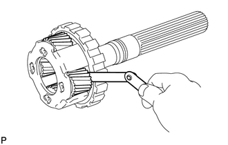 (a) Using a feeler gauge, measure the rear planetary gear pinion thrust clearance. Standard clearance: 0.2 to 0.6 mm (0.00787 to 0.0236 in.) Maximum clearance: 0.65 mm (0.0256 in.)
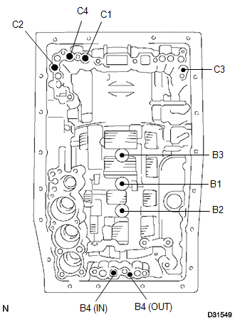
27. INSPECT 1ST AND REVERSE BRAKE RETURN SPRING SUB-ASSEMBLY 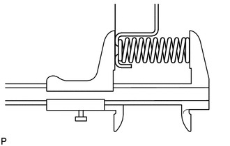 (a) Using a vernier caliper, measure the free length of the spring together with the spring seat. Standard free length: 23.74 mm (0.935 in.) If the free length is less than the standard, replace the 1st and reverse brake return spring sub-assembly. 28. INSPECT INDIVIDUAL PISTON OPERATION
|
Toyota Tundra Service Manual > Audio And Visual System: HD Radio Tuner Malfunction (B1551,B15A0,B15B0,B15B3-B15B5,B15B7)
DESCRIPTION These DTCs are stored when a malfunction occurs in the radio and display receiver assembly. DTC Code DTC Detection Condition Trouble Area B1551 When one of the conditions below is met: "HD Radio" tuner decoder malfunction "HD Radio" tuner audio output section malfunction "HD Radio" tuner ...