INSPECTION PROCEDURE 1. INSPECT SHIFT SOLENOID VALVE SL1 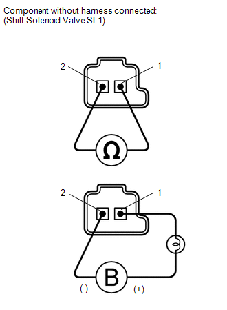 (a) Measure the resistance according to the value(s) in the table below. Standard Resistance:
(b) Apply 12 V battery voltage to the shift solenoid valve and check that the valve moves and makes an operating noise. OK:
If the result is not as specified, replace the solenoid valve. 2. INSPECT SHIFT SOLENOID VALVE S1  (a) Measure the resistance according to the value(s) in the table below. Standard Resistance:
(b) Apply 12 V battery voltage to the shift solenoid valve and check that the valve moves and makes an operating noise. OK:
If the result is not as specified, replace the solenoid valve. 3. INSPECT SHIFT SOLENOID VALVE S2 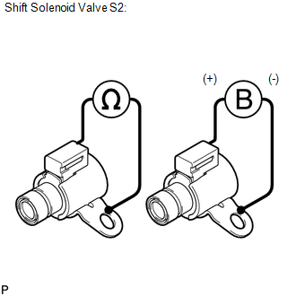 (a) Measure the resistance according to the value(s) in the table below. Standard Resistance:
(b) Apply 12 V battery voltage to the shift solenoid valve and check that the valve moves and makes an operating noise. OK:
If the result is not as specified, replace the solenoid valve. 4. INSPECT SHIFT SOLENOID VALVE S3 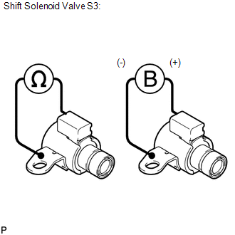 (a) Measure the resistance according to the value(s) in the table below. Standard Resistance:
(b) Apply 12 V battery voltage to the shift solenoid valve and check that the valve moves and makes an operating noise. OK:
If the result is not as specified, replace the solenoid valve. 5. INSPECT SHIFT SOLENOID VALVE S4 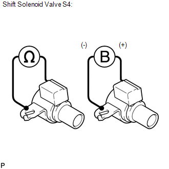 (a) Measure the resistance according to the value(s) in the table below. Standard Resistance:
(b) Apply 12 V battery voltage to the shift solenoid valve and check that the valve moves and makes an operating noise. OK:
If the result is not as specified, replace the solenoid valve. 6. INSPECT SHIFT SOLENOID VALVE SL2  (a) Measure the resistance according to the value(s) in the table below. Standard Resistance:
(b) Apply 12 V battery voltage to the shift solenoid valve and check that the valve moves and makes an operating noise. OK:
If the result is not as specified, replace the solenoid valve. 7. INSPECT SHIFT SOLENOID VALVE SR 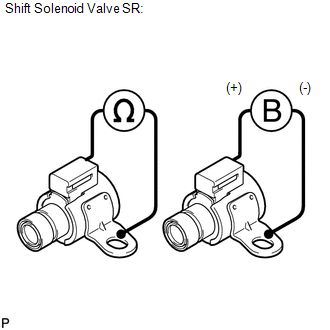 (a) Measure the resistance according to the value(s) in the table below. Standard Resistance:
(b) Apply 12 V battery voltage to the shift solenoid valve and check that the valve moves and makes an operating noise. OK:
If the result is not as specified, replace the solenoid valve. 8. INSPECT SHIFT SOLENOID VALVE SLT  (a) Measure the resistance according to the value(s) in the table below. Standard Resistance:
(b) Apply 12 V battery voltage to the shift solenoid valve and check that the valve moves and makes an operating noise. OK:
If the result is not as specified, replace the solenoid valve. 9. INSPECT SHIFT SOLENOID VALVE SLU 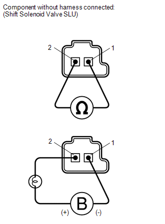 (a) Measure the resistance according to the value(s) in the table below. Standard Resistance:
(b) Apply 12 V battery voltage to the shift solenoid valve and check that the valve moves and makes an operating noise. OK:
If the result is not as specified, replace the solenoid valve. |
Toyota Tundra Service Manual > Forward Recognition Camera System: Steering Angle Sensor (C1A47)
DESCRIPTION The forward recognition camera receives steering angle information from the spiral with sensor cable sub-assembly. If the forward recognition camera detects a spiral with sensor cable sub-assembly malfunction, DTC C1A47 is stored. DTC No. Detection Item DTC Detection Condition Trouble Ar ...


