INSTALLATION CAUTION / NOTICE / HINT HINT:
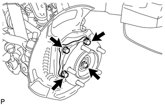
PROCEDURE 1. INSTALL FRONT AXLE HUB SUB-ASSEMBLY LH (for 2WD) (a) Apply MP grease to a new O-ring. (b) Install the O-ring to the axle hub. NOTICE: Do not damage the O-ring.
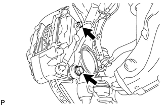
2. INSTALL FRONT AXLE HUB SUB-ASSEMBLY LH (for 4WD) (a) Apply MP grease to a new O-ring. (b) Install the O-ring to the axle hub. NOTICE: Do not damage the O-ring. (c) Connect the front drive shaft to the front axle hub. NOTICE: Be careful not to damage the front drive shaft boot.
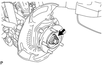
3. INSTALL FRONT AXLE HUB NUT LH (for 4WD) (a) Clean the threaded parts on the drive shaft and axle hub nut using a non-residue solvent. NOTICE:
(b) Using a 39 mm socket wrench, install the hub nut. Torque: 338 N·m {3446 kgf·cm, 249 ft·lbf}
4. INSPECT FRONT AXLE HUB (a) Inspect the front axle hub (see page
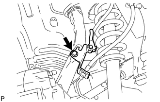
5. INSTALL FRONT AXLE HUB GREASE CAP LH (for 4WD) (a) Install the axle hub grease cap. NOTICE: Make sure to securely fit the bearing to the axle hub. 6. INSTALL FRONT DISC LH 7. CONNECT FRONT DISC BRAKE CALIPER ASSEMBLY LH
8. INSTALL FRONT WHEEL Torque: for Aluminum Wheel : 131 N·m {1336 kgf·cm, 97 ft·lbf} for steel Wheel : 209 N·m {2131 kgf·cm, 154 ft·lbf} 9. CHECK SPEED SENSOR SIGNAL (a) Check the speed sensor signal (see page |
Toyota Tundra Service Manual > Hood: On-vehicle Inspection
ON-VEHICLE INSPECTION PROCEDURE 1. INSPECT HOOD SUB-ASSEMBLY (a) Check that the clearance measurements of areas A to D are within the standard range. Standard Clearance: Area Specified Condition A 3.7 to 6.7 mm (0.146 to 0.264 in.) B -1.5 to 1.5 mm (-0.0591 to 0.0591 in.) C (Reference) 25.25 to 28.2 ...

 ).
).