REMOVAL CAUTION / NOTICE / HINT HINT:
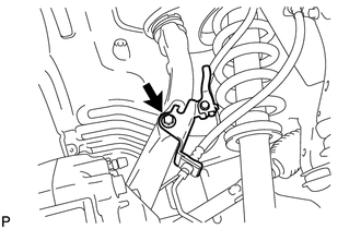
PROCEDURE 1. REMOVE FRONT WHEEL 2. DISCONNECT FRONT DISC BRAKE CALIPER ASSEMBLY LH
3. REMOVE FRONT DISC LH 4. REMOVE FRONT AXLE HUB GREASE CAP LH (for 4WD)
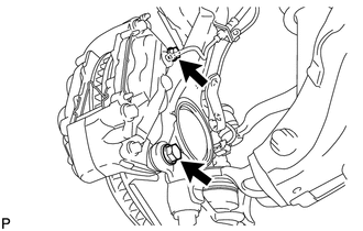
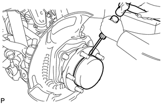
5. REMOVE FRONT AXLE HUB NUT LH (for 4WD)
(b) Using a 39 mm socket wrench, remove the axle hub nut. 6. REMOVE FRONT AXLE HUB SUB-ASSEMBLY LH (for 2WD)
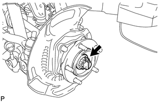
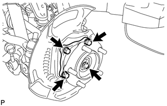
(b) Remove the axle hub and dust cover from the steering knuckle. (c) Remove the O-ring from the axle hub. 7. REMOVE FRONT AXLE HUB SUB-ASSEMBLY LH (for 4WD)
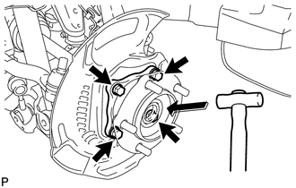
(b) Using a plastic-faced hammer, tap out the front drive shaft from the front axle hub. NOTICE: Be careful not to damage the drive shaft boot. (c) Remove the axle hub and dust cover from the steering knuckle. (d) Remove the O-ring from the axle hub. |
Toyota Tundra Service Manual > Brake Pedal: Removal
REMOVAL PROCEDURE 1. REMOVE PRECAUTION NOTICE: After turning the ignition switch off, waiting time be required before disconnecting the cable from the battery terminal. Therefore, make sure to read the disconnecting the cable from the battery terminal notice before proceeding with work (See page ). ...