REMOVAL CAUTION / NOTICE / HINT HINT:
PROCEDURE 1. REMOVE FRONT AXLE HUB SUB-ASSEMBLY LH (a) Remove the front axle hub (see page 2. DISCONNECT FRONT SPEED SENSOR LH
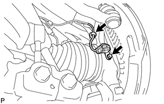
(b) Disconnect the speed sensor from the steering knuckle. 3. DISCONNECT TIE ROD END SUB-ASSEMBLY LH (a) Remove the cotter pin and nut.
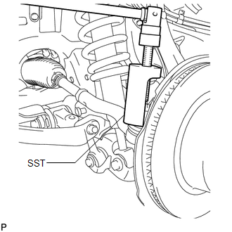
4. DISCONNECT FRONT LOWER BALL JOINT ATTACHMENT LH
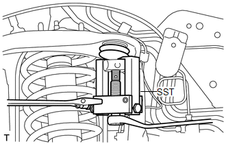
5. REMOVE STEERING KNUCKLE LH (a) Support the front suspension lower arm LH with a jack. (b) Remove the clip and the nut.
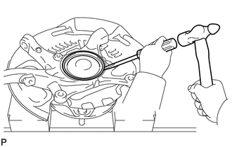
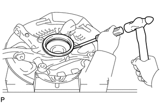
(d) Remove the steering knuckle. 6. REMOVE KNUCKLE GREASE RETAINER CAP LH (for 2WD)
7. REMOVE STEERING KNUCKLE OIL SEAL LH (for 4WD)
|
Toyota Tundra Service Manual > Automatic Transmission System: System Description
SYSTEM DESCRIPTION 1. SYSTEM DESCRIPTION (a) The Electronic Controlled Automatic Transmission (ECT) is an automatic transmission that electronically controls shift timing using the Engine Control Module (ECM). The ECM detects electrical signals that indicate engine and driving conditions, and contro ...

 ).
).