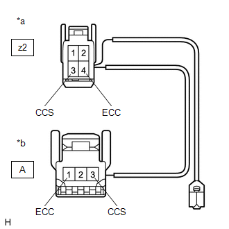
DESCRIPTION The cruise control main switch is used to turn the cruise control system on and off, as well as operate 7 functions: SET, - (COAST), TAP-DOWN, RES (RESUME), + (ACCEL), TAP-UP and CANCEL. The SET, TAP-DOWN and - (COAST) functions, and the RES (RESUME), TAP-UP and + (ACCEL) functions are operated with the same switch. The cruise control main switch is an automatic return type switch which turns on only while operating it in the direction of each arrow and turns off after releasing it. The internal contact points of the cruise control main switch turn on with switch operation. Then the ECM reads the voltage value that has been changed by the switch operation to control the SET, - (COAST), RES (RESUME), + (ACCEL), and CANCEL functions. WIRING DIAGRAM 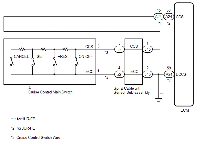 CAUTION / NOTICE / HINT NOTICE: The vehicle is equipped with a Supplemental Restraint System (SRS) which includes components such as airbags. Before servicing (including removal or installation of parts), be sure to read the precaution for Supplemental Restraint System. Click here PROCEDURE
(a) Connect the Techstream to the DLC3. (b) Turn the ignition switch ON. (c) Turn the Techstream on. (d) Enter the following menus: Powertrain / Cruise Control / Data List. (e) Read the Data List according to the display on the Techstream. Powertrain > Cruise Control > Data List
OK: When the cruise control main switch is operated, the display changes as shown above.
(a) Remove the cruise control main switch. Click here (b) Inspect the cruise control main switch. Click here
(b) Disconnect the cruise control main switch connector. (c) Measure the resistance according to the value(s) in the table below. Standard Resistance:
(a) Remove the spiral cable with sensor sub-assembly. Click here
(b) Inspect the spiral cable with sensor sub-assembly. Click here
(a) for 1UR-FE: (1) Disconnect the J45 spiral cable with sensor sub-assembly connector. (2) Disconnect the A24 ECM connector. (3) Measure the resistance according to the value(s) in the table below. Standard Resistance:
(b) for 3UR-FE: (1) Disconnect the J45 spiral cable with sensor sub-assembly connector. (2) Disconnect the A24 ECM connector. (3) Measure the resistance according to the value(s) in the table below. Standard Resistance:
|
Toyota Tundra Service Manual > Theft Deterrent System: Check For Intermittent Problems
CHECK FOR INTERMITTENT PROBLEMS NOTICE: If the vehicle or vehicle controls are operated (for example, during initial inspection when the vehicle is brought in for repair) before operation history has been read out and saved, the operation history information could be lost. The function "Read op ...