TERMINALS OF ECU CHECK ECM (for 1UR-FE) 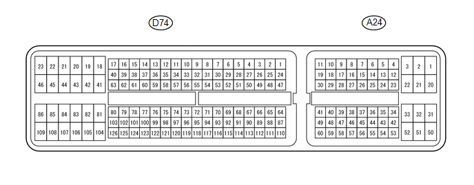 HINT: The standard voltage, resistance and waveform between each pair of the ECM terminals is shown in the table below. The appropriate conditions for checking each pair of the terminals is also indicated. The result of checks should be compared with the standard voltage, resistance and waveform for each pair of the terminals as displayed in the Specified Condition column. The illustration above can be used as a reference to identify the ECM terminal locations.
CHECK ECM (for 3UR-FE)  HINT: The standard voltage, resistance and waveform between each pair of the ECM terminals is shown in the table below. The appropriate conditions for checking each pair of the terminals is also indicated. The result of checks should be compared with the standard voltage, resistance and waveform for each pair of the terminals as displayed in the Specified Condition column. The illustration above can be used as a reference to identify the ECM terminal locations.
|
Toyota Tundra Service Manual > Audio And Visual System: XM Tuner Malfunction (B15BA)
DESCRIPTION This DTC is stored when a malfunction occurs in the extension module. DTC Code DTC Detection Condition Trouble Area B15BA When either of the conditions below is met: Internal IC malfunction Tuner malfunction Stereo component tuner assembly CAUTION / NOTICE / HINT NOTICE: After replacing ...


