DESCRIPTION Detection condition 1:
- When the brake pedal is depressed, the stop light switch assembly
outputs a signal to the ECM. When the ECM receives the signal, it
cancels control of vehicle speed by the dynamic radar cruise control
system. The fail-safe function operates to enable normal operation even
if there is a malfunction in the stop light signal circuit. The
cancellation condition occurs when voltage is applied to terminal STP.
When the brake pedal is depressed, voltage is applied to terminal STP of
the ECM through the STOP fuse and the stop light switch assembly, and
the ECM turns the dynamic radar cruise control system off.
Detection condition 2:
- The ECM receives the brake demand signal from the millimeter wave radar
sensor assembly and transmits it to the skid control ECU (brake actuator
assembly). The skid control ECU (brake actuator assembly) receives a
signal from the ECM and operates the skid control ECU (brake actuator
assembly). The skid control ECU (brake actuator assembly) operates the
brake actuator assembly and illuminates the stop lights.
|
DTC No. | Detection Item |
DTC Detection Condition | Trouble Area | |
P0571 | Brake Switch "A" Circuit | Condition 1:
- While the vehicle speed is 36 km/h (22 mph) or more and the dynamic
radar cruise control system is operating, voltage of STP terminal and
that of ST1- terminal of ECM are less than 1 V for approximately 0.5
seconds or more.
Condition 2:
- While the vehicle speed is 36 km/h (22 mph) or more and the dynamic
radar cruise control system is operating, the ECM receives error signal
from the skid control ECU (brake actuator assembly) for approximately
0.5 seconds or more.
| Condition 1:
- Stop light switch assembly
- Harness or connector
- ECM
Condition 2:
- ECM
- Vehicle stability control system
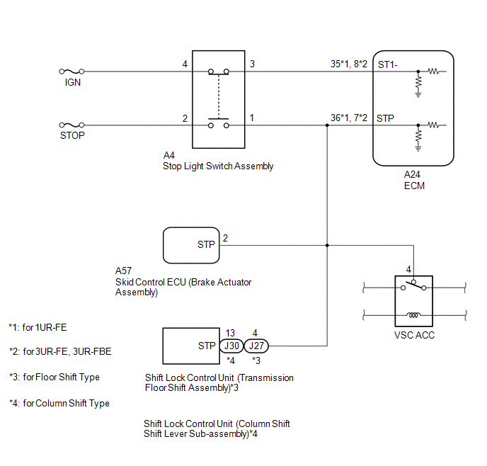
| WIRING DIAGRAM
 CAUTION / NOTICE / HINT
NOTICE:
- Inspect the fuses for circuits related to this system before performing the following procedure.
- Before replacing the ECM, refer to Registration.
Click here 
PROCEDURE |
1. | CHECK FOR DTCs (VEHICLE STABILITY CONTROL SYSTEM) |
(a) Check for DTCs. Click here
HINT: When
DTC P0571 (detection condition 2) is stored by the dynamic radar cruise
control system, DTC C1380 is stored by the vehicle stability control
system. Therefore, if DTC P0571 (detection condition 2) is stored,
inspect the vehicle stability control system first.
|
Result | Proceed to | |
Vehicle stability control system DTCs are not output |
A | | Vehicle stability control system DTCs are output |
B |
| B |
 | GO TO VEHICLE STABILITY CONTROL SYSTEM |
|
A |
 | |
| 2. |
CHECK FOR DTC (RADAR CRUISE1) | (a) Clear the DTCs.
Click here (b) Make sure that the DTC detection conditions are met.
HINT: If the detection conditions are not met, the system cannot detect the malfunction.
- Turn the ignition switch to ON.
- Turn the dynamic radar cruise control system on using the cruise control main switch (ON-OFF button).
- Drive the vehicle at 36 km/h (22 mph) or more for 1 second or more.
(c) Check for DTCs. Click here
|
Result | Proceed to | |
DTC P0571 is not output |
A | | DTC P0571 is output |
B |
| A |
| USE SIMULATION METHOD TO CHECK |
|
B | |
| |
| 3. |
CHECK HARNESS AND CONNECTOR (STOP LIGHT SWITCH ASSEMBLY - BATTERY AND BODY GROUND) |
| (a) Disconnect the stop light switch assembly connector. |
 |
|
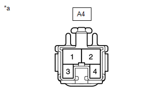
*a | Front view of wire harness connector
(to Stop Light Switch Assembly) | | |
(b) Measure the voltage according to the value(s) in the table below. Standard Voltage: |
Tester Connection | Condition |
Specified Condition | |
A4-2 - Body ground | Always |
11 to 14 V | |
A4-4 - Body ground | Ignition switch to ON |
11 to 14 V | |
A4-4 - Body ground | Ignition switch off |
Below 1 V |
| NG |
| REPAIR OR REPLACE HARNESS OR CONNECTOR |
|
OK | |
| |
| 4. |
INSPECT STOP LIGHT SWITCH ASSEMBLY | (a) Inspect the stop light switch assembly.
Click here
| NG |
| REPLACE STOP LIGHT SWITCH ASSEMBLY |
|
OK | |
| |
| 5. |
CHECK HARNESS AND CONNECTOR (ECM - STOP LIGHT SWITCH ASSEMBLY) |
(a) Disconnect the A24 ECM connector. (b) Disconnect the A4 stop light switch assembly connector.
(c) Disconnect the A57 skid control ECU (brake actuator assembly) connector.
(d) Disconnect the J27*1 or J30*2 shift lock control unit connector.
- *1: for Floor shift type
- *2: for Column shift type
(e) Remove the VSC ACC relay from the engine room relay block. (f) Measure the resistance according to the value(s) in the table below.
Standard Resistance (for 1UR-FE): |
Tester Connection | Condition |
Specified Condition | |
A24-35 (ST1-) - A4-3 |
Always | Below 1 Ω | |
A24-36 (STP) - A4-1 | Always |
Below 1 Ω | |
A24-35 (ST1-) or A4-3 - Body ground |
Always | 10 kΩ or higher | |
A24-36 (STP) or A4-1 - Body ground |
Always | 10 kΩ or higher |
Standard Resistance (for 3UR-FE, 3UR-FBE): |
Tester Connection | Condition |
Specified Condition | |
A24-8 (ST1-) - A4-3 | Always |
Below 1 Ω | |
A24-7 (STP) - A4-1 | Always |
Below 1 Ω | |
A24-8 (ST1-) or A4-3 - Body ground |
Always | 10 kΩ or higher | |
A24-7 (STP) or A4-1 - Body ground |
Always | 10 kΩ or higher |
| OK |
| REPLACE ECM |
| NG |
| REPAIR OR REPLACE HARNESS OR CONNECTOR | | 

