|
Sender | Receiver |
Signal | Line |
|
Millimeter Wave Radar Sensor Assembly |
Forward Recognition Camera |
- Pre-collision alarm signal
- Brake assist standby signal
- Pre-collision brake operation signal
| CAN |
|
ECM | Forward Recognition Camera |
- Shift position signal (P, R, N, D)
- Engine type information signal
- Vehicle specification information (2WD/4WD information, conventional/ hybrid information)
| CAN |
|
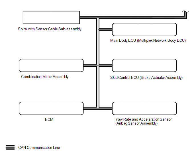
Skid Control ECU (Brake Actuator Assembly) |
Forward Recognition Camera |
- Vehicle speed signal
- Stop light switch signal
- Vehicle yaw rate sensor zero point malfunction signal
- Vehicle stability control system operation signal
- Vehicle stability control system malfunction signal
| CAN |
|
Yaw Rate and Acceleration Sensor (Airbag Sensor Assembly) |
Forward Recognition Camera | Vehicle yaw rate sensor signal |
CAN |
| Main Body ECU (Multiplex Network Body ECU) |
Forward Recognition Camera |
Destination information signal |
CAN |
 Communication Table

