PARTS LOCATION ILLUSTRATION 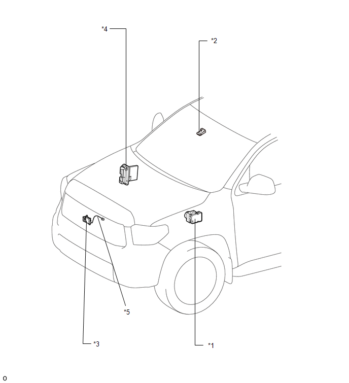
ILLUSTRATION 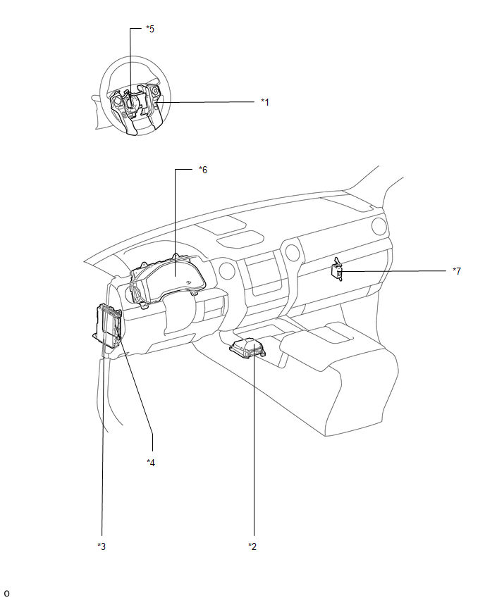
|
Toyota Tundra Service Manual > Power Window Control System(w/o Jam Protection Function): Power Windows do not Operate at All
DESCRIPTION If all of the power windows do not operate, the master switch may have no power or may be malfunctioning. WIRING DIAGRAM PROCEDURE 1. CHECK HARNESS AND CONNECTOR (MASTER SWITCH - BATTERY AND BODY GROUND) *a Front view of wire harness connector (to Master Switch) (a) Disconnect the N2 mas ...


