|
Sender ECU | Receiver ECU |
Signal | Line |
|
Forward Recognition Camera | Combination Meter Assembly |
- Lane departure alert indicator light signal
- Lane marker signal
- Forward Recognition Camera malfunction signal
- LDA customization information
- Break message and exertion level display
- Lane departure alert buzzer signal
- Lane departure alert main switch operation signal
| CAN |
|
ECM | Forward Recognition Camera |
- Shift position signal (P, R, N, D)
- Vehicle specification information (2WD/4WD information, conventional/hybrid information)
| CAN |
|
Skid Control ECU (Brake Actuator Assembly) |
- Wheel speed signal
- Wheel speed sensor malfunction signal
- Under VSC control
- Under TRAC control
- Airbag sensor assembly zero point signal
- Airbag sensor assembly zero point error signal
| CAN |
|
Combination Meter Assembly |
- Turn signal light switch signal
- Vehicle speed tolerance signal
| CAN |
|
Spiral with Sensor Cable Sub-assembly |
- Steering signal
- Steering angle sensor malfunction signal
| CAN |
|
Yaw Rate and Acceleration Sensor (Airbag Sensor Assembly) |
- Yaw rate sensor signal
- Yaw rate sensor voltage signal
- Yaw rate sensor malfunction signal
| CAN |
|
Main Body ECU (Multiplex Network Body ECU) |
- Country specification information signal
- Steering wheel information signal
| CAN |
|
ECM | Accelerator opening angle percentage signal |
CAN |
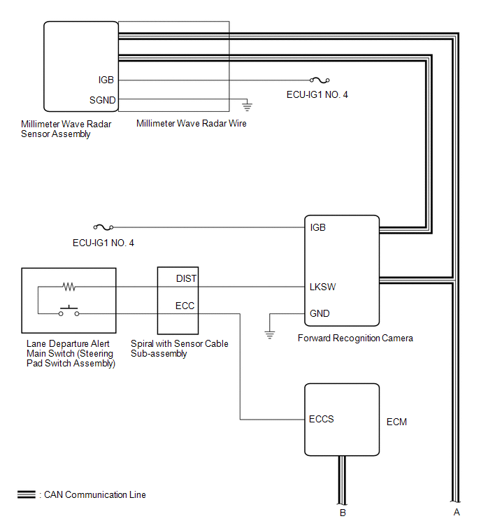
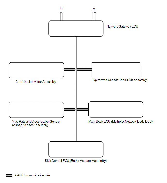 Communication Table

