COMPONENTS ILLUSTRATION 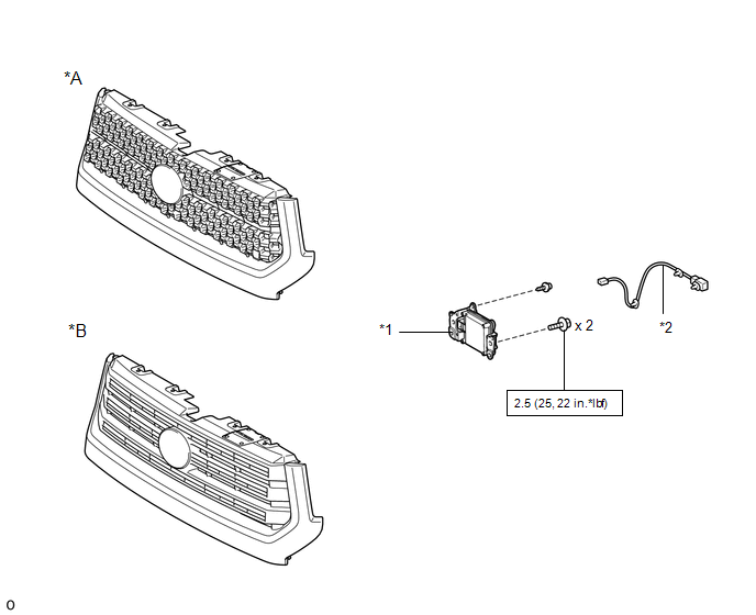
ILLUSTRATION 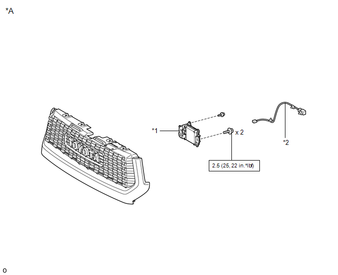
|
Toyota Tundra Service Manual > Brake Booster: Components
COMPONENTS ILLUSTRATION *1 BRAKE BOOSTER ASSEMBLY *2 BRAKE MASTER CYLINDER SUB-ASSEMBLY *3 BRAKE TUBE *4 BRAKE VACUUM CHECK VALVE ASSEMBLY *5 NO. 3 AIR DUCT SUB-ASSEMBLY *6 PUSH ROD PIN *7 VACUUM HOSE ASSEMBLY *8 CLEVIS *9 BRAKE BOOSTER GASKET *10 BRAKE MASTER CYLINDER SEAL *11 NO. 2 BRAKE TUBE CLAM ...


