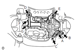
INSTALLATION PROCEDURE 1. INSTALL FRONT DIFFERENTIAL CARRIER ASSEMBLY
(b) Using a jack, slowly raise the front differential carrier assembly to its installation position. (c) Temporarily install the A, B, C, D and E bolts. (d) Tighten the A bolt. Torque: 113 N·m {1152 kgf·cm, 83 ft·lbf} (e) Tighten the B and C bolts. Torque: 113 N·m {1152 kgf·cm, 83 ft·lbf} (f) Tighten the D and E bolts. Torque: 113 N·m {1152 kgf·cm, 83 ft·lbf} (g) Connect the differential actuator hose. (h) Connect the differential actuator connector. 2. INSTALL FRONT DRIVE SHAFT ASSEMBLY LH (See page 3. INSTALL FRONT DRIVE SHAFT ASSEMBLY RH HINT: Use the same procedure as the LH side. 4. INSTALL FRONT PROPELLER SHAFT ASSEMBLY (See page 5. ADD DIFFERENTIAL OIL 6. INSTALL NO. 1 ENGINE UNDER COVER 7. INSTALL FRONT WHEEL (a) Install the front wheels. Torque: for aluminum wheel : 131 N·m {1336 kgf·cm, 97 ft·lbf} for steel wheel : 209 N·m {2131 kgf·cm, 154 ft·lbf} |
Toyota Tundra Service Manual > Audio And Visual System: Terminals Of Ecu
TERMINALS OF ECU 1. RADIO AND DISPLAY RECEIVER ASSEMBLY Terminal No. (Symbol) Wiring Color Terminal Description Condition Specified Condition J137-1 (FR+) - J137-7 (GND1) LA-LG - BR Sound signal (Front right) Audio system playing A waveform synchronized with sound is output J137-2 (FL+) - J137-7 (GN ...

 )
)
