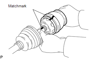
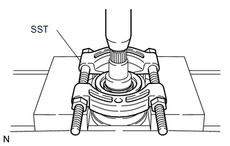
DISASSEMBLY PROCEDURE 1. REMOVE INBOARD JOINT BOOT CLAMP (a) Using a side cutter, cut the 2 inboard joint boot clamps and remove them. 2. DISCONNECT INBOARD JOINT BOOT (a) Disconnect the inboard joint boot from the inboard joint shaft. 3. REMOVE INBOARD JOINT SHAFT
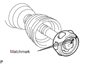
(b) Using a screwdriver, remove the snap ring from the outboard joint shaft. (c) Remove the inboard joint shaft from the outboard joint shaft.
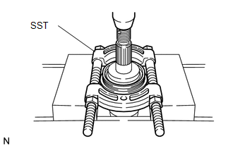
(e) Remove the 6 balls. (f) Slide the cage to the outboard joint side.
(i) Remove the cage. 4. REMOVE INBOARD JOINT BOOT (a) Remove the inboard joint boot from the outboard joint shaft. 5. REMOVE OUTBOARD JOINT BOOT CLAMP (a) Using a side cutter, cut the 2 outboard joint boot clamps and remove them. 6. REMOVE OUTBOARD JOINT BOOT (a) Remove the outboard joint boot from the outboard joint shaft. 7. REMOVE FRONT DRIVE SHAFT DUST COVER LH
8. REMOVE DUST SEAL
|
Toyota Tundra Service Manual > Power Window Control System(w/o Jam Protection Function): Operation Check
OPERATION CHECK 1. CHECK WINDOW LOCK SWITCH (a) Check that the front passenger side power window and rear power windows cannot be operated when the window lock switch of the master switch is pressed. OK: Operation of front passenger side power window and rear power windows are disabled. (b) Check th ...