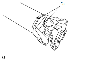
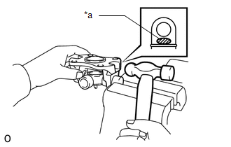
DISASSEMBLY PROCEDURE 1. REMOVE FRONT PROPELLER SHAFT JOINT SPIDER BEARING SNAP RING
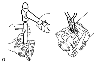
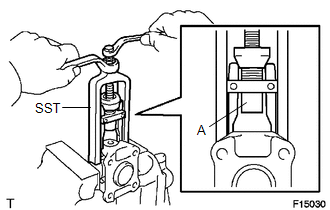
(c) Using needle-nose pliers, remove the 4 snap rings from the grooves. 2. REMOVE SPIDER BEARING 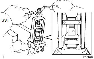 (a) Using SST, push out the bearing from the flange yoke. SST: 09332-25010 HINT: Before installing SST, sufficiently raise the part labeled A. If part A is too low, SST may be difficult to install.
(d) Using SST, push the bearing out of the flange yoke. SST: 09332-25010 HINT: Before installing SST, sufficiently raise the part labeled A. If part A is too low, SST may be difficult to install.
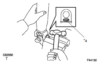
(f) Remove the spider. Text in Illustration
HINT: Remove the bearing on the opposite side using the same procedure. |
Toyota Tundra Service Manual > Front Camera: Before Starting Adjustment
BEFORE STARTING ADJUSTMENT CAUTION / NOTICE / HINT NOTICE: When replacing the windshield glass of a vehicle equipped with a forward recognition camera, make sure to use a Toyota genuine part. If a non-Toyota genuine part is used, the forward recognition camera may not be able to be installed due to ...