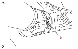
INSTALLATION PROCEDURE 1. INSTALL FRONT PROPELLER SHAFT (a) Completely remove any oil or the like and clean the contact surfaces of the propeller shaft flange, differential flange and transfer flange. (b) for Front Differential Side:
(2) Install the propeller shaft with the 4 washers and 4 nuts. Torque: 80 N·m {819 kgf·cm, 59 ft·lbf}
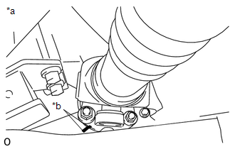
2. INSTALL PROPELLER SHAFT HEAT INSULATOR BRACKET SUB-ASSEMBLY (a) Install the heat insulator bracket to the crossmember with the 2 bolts. Torque: 16 N·m {160 kgf·cm, 12 ft·lbf} 3. INSTALL PROPELLER SHAFT HEAT INSULATOR 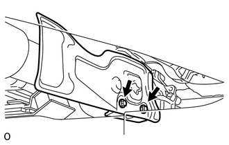 (a) Install the heat insulator to the heat insulator bracket with the 2 bolts. Torque: 16 N·m {160 kgf·cm, 12 ft·lbf} |
Toyota Tundra Service Manual > Audio And Visual System: XM Tuner Malfunction (B15BA)
DESCRIPTION This DTC is stored when a malfunction occurs in the extension module. DTC Code DTC Detection Condition Trouble Area B15BA When either of the conditions below is met: Internal IC malfunction Tuner malfunction Stereo component tuner assembly CAUTION / NOTICE / HINT NOTICE: After replacing ...