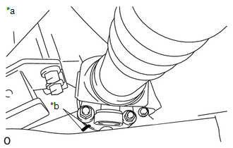
REMOVAL PROCEDURE 1. REMOVE PROPELLER SHAFT HEAT INSULATOR  (a) Remove the 2 bolts and heat insulator from the heat insulator bracket. 2. REMOVE PROPELLER SHAFT HEAT INSULATOR BRACKET SUB-ASSEMBLY (a) Remove the 2 bolts and heat insulator bracket from the crossmember. 3. REMOVE FRONT PROPELLER SHAFT ASSEMBLY 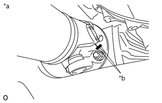 (a) for Front Differential Side: (1) Place matchmarks on the differential and propeller shaft flange. Text in Illustration
(2) Remove the 4 nuts, 4 washers and disconnect the propeller shaft from the differential. NOTICE: Use a rope to suspend the front edge of the propeller shaft.
(c) Remove the propeller shaft from the transfer flange. |
Toyota Tundra Service Manual > Rear Seat Assembly(for Crewmax Rh Side): Installation
INSTALLATION PROCEDURE 1. INSTALL REAR OUTER SEAT LEG BRACKET SUB-ASSEMBLY RH (a) Install rear outer seat leg bracket sub-assembly RH with the 2 bolts. Torque: 42 N·m {428 kgf·cm, 31 ft·lbf} 2. INSTALL REAR INNER SEAT LEG BRACKET SUB-ASSEMBLY RH (a) Install rear inner seat leg bracket sub-assembl ...