INSTALLATION PROCEDURE 1. MEASURE EXTENSION HOUSING AND DIFFERENTIAL FLANGE ANGLE
NOTICE:
- Perform the inspection on a level surface.
- Perform the inspection with the vehicle empty.
- Perform the inspection with all wheels on the ground.
HINT: As the
extension housing and rear differential flange angles are necessary when
measuring the installation angle of the propeller shaft, measure the
angle of the extension housing and rear differential flange before
installing the propeller shaft.
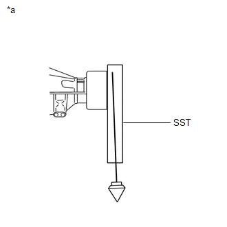
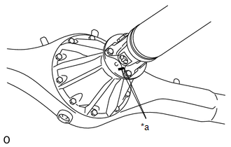
| (a) Using SST, measure and record the angle of the extension housing flange (A).
SST: 09370-50010 Text in Illustration |
*a | Extension Housing Flange Angle: A | |
|
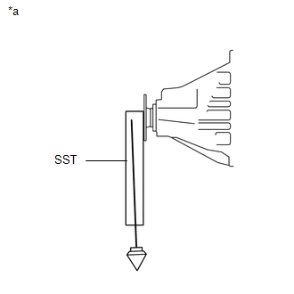
| (b) Using SST, measure and record the angle of the rear differential flange (B).
SST: 09370-50010 Text in Illustration |
*a | Rear Differential Flange Angle: B | |
|
2. TEMPORARILY INSTALL PROPELLER WITH CENTER BEARING SHAFT ASSEMBLY (a) Completely remove any oil or the like and clean the contact surfaces of the propeller shaft flange and differential flange.
(b) for 1UR-FE: Remove SST from the transmission. SST: 09325-40010
(c) for 3UR-FE: Remove SST from the transmission. SST: 09325-60010
(d) Insert the sleeve yoke into the transmission. (e) w/o Bearing Washer:
| (1) Temporarily install the center support bearing to the crossmember with the 2 mounting bolts. |
|
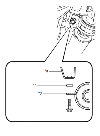
(f) w/ Bearing Washer: |
(1) Temporarily install the center support bearing to the crossmember with the 2 bearing washers and 2 mounting bolts. Text in Illustration |
*1 | No. 2 Center Support Bearing Washer | |
*2 | No. 1 Center Support Bearing Assembly | |
*a | Frame | |
|
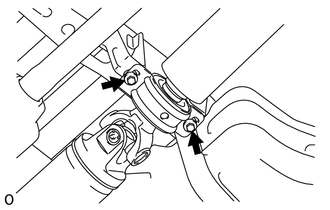
| (g) Align the matchmarks on the propeller shaft flange and differential flange. Text in Illustration |
|
(h) Connect the propeller shaft to the differential side, and install the 4 bolts and 4 nuts.
Torque: 70 N·m {714 kgf·cm, 52 ft·lbf} 3. TIGHTEN PROPELLER WITH CENTER BEARING SHAFT ASSEMBLY
(a)
With the vehicle empty and all 4 tires supported by a lift, or with the
vehicle suspension in the full rebound position, adjust the center
bearing so that dimension A (the distance from the front surface of the
center bearing housing to the back surface of the intermediate shaft) is
as shown in the chart below. HINT: Measure
dimension A (the distance from the front surface of the center bearing
housing to the back surface of the intermediate shaft) at 3 places and
make adjustments so that the measured dimensions are equal.
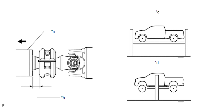 Text in Illustration Text in Illustration |
*a | Intermediate Shaft |
*b | Dimension A | |
*c | Tires supported and vehicle empty (When using drive-on type lift) |
*d | Full rebound position (When using 2 post lift) |
 |
Front Side | - |
- | Standard Dimension A: |
Vehicle Model |
Dimension A | | Tires supported and vehicle empty
(When using drive-on type lift) |
Full rebound position (When using 2 post lift) | |
UPK51L-CRTSKA | 24.0 mm (0.945 in.) |
16.0 mm (0.630 in.) | |
UPK51L-PSTSKA | 24.0 mm (0.945 in.) |
16.0 mm (0.630 in.) | |
USK51L-CRTLKA |
24.0 mm (0.945 in.) |
16.0 mm (0.630 in.) | |
USK51L-CRTLKA*1 | |
USK51L-CRTSKA |
24.0 mm (0.945 in.) |
16.0 mm (0.630 in.) | |
USK51L-CRTSKA*1 | |
USK51L-CRTSKA*2 | |
USK51L-CRTSKA*3 | 24.0 mm (0.945 in.) |
16.0 mm (0.630 in.) | |
USK51L-PSTLKA |
24.0 mm (0.945 in.) |
16.0 mm (0.630 in.) | |
USK51L-PSTLKA*1 | |
USK51L-PSTSKA |
24.0 mm (0.945 in.) |
16.0 mm (0.630 in.) | |
USK51L-PSTSKA*1 | |
USK51L-PSTSKA*2 | |
USK51L-PSTZKA | 24.0 mm (0.945 in.) |
16.0 mm (0.630 in.) | |
USK51L-PSTZKA*1 | 24.0 mm (0.945 in.) |
16.0 mm (0.630 in.) | |
USK52L-CHTSKA |
22.0 mm (0.866 in.) |
16.0 mm (0.630 in.) | |
USK52L-CHTSKA*1 | *1: includes Off road package
*2: includes Sports package *3: includes YOUTH Edition package
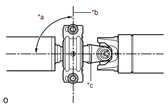
| (b) Check that the center line of the bracket is at right angles to the shaft axial direction. Text in Illustration |
*a | 90° | |
*b | Bracket Center Line | |
*c | Shaft Axial Direction | |
|
(c) Tighten the 2 mounting bolts. Torque: 40 N·m {410 kgf·cm, 30 ft·lbf}
4. INSPECT PROPELLER SHAFT ANGLE
NOTICE:
- Perform the inspection on a level surface.
- Perform the inspection with the vehicle empty.
- Perform the inspection with all wheels on the ground.
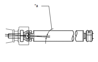
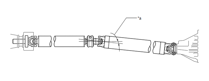
(a) Measure the No. 1 joint angle. (1) Using SST, measure and record the angle of the intermediate shaft (C).
SST: 09370-50010 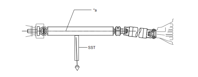 Text in Illustration Text in Illustration |
*a | Intermediate Shaft Angle: C |
- | - |
| (2)
Subtract the angle of the extension housing flange (A) measured before
installing the propeller shaft from the angle of the intermediate shaft
(C) to calculate the No. 1 joint angle. Text in Illustration
No. 1 joint angle: Angle of intermediate shaft (C) - Angle of extension housing flange (A)
Measured Value (Reference): |
Intermediate Shaft Angle Measured Value (C) |
Extension Housing Flange Angle Measured Value (A) |
No. 1 Joint Angle (Calculated Value) (C) - (A) | |
3°15' (3.25°) | 4°00' (4.00°) |
-0°45' (-0.75°) |
HINT:
- Using the following chart, check if the calculated No. 1 joint angle is within the specified value.
- The tolerance is +/-0°60' (1.00°).
Standard No. 1 Joint Angle: |
Vehicle Model | No. 1 Joint Angle | |
UPK51L-CRTSKA | 0°41' +/-0°60' (0.68° +/-1.00°) | |
UPK51L-PSTSKA | 0°41' +/-0°60' (0.68° +/-1.00°) | |
USK51L-CRTLKA |
0°41' +/-0°60' (0.68° +/-1.00°) | |
USK51L-CRTLKA*1 | |
USK51L-CRTSKA |
0°41' +/-0°60' (0.68° +/-1.00°) | |
USK51L-CRTSKA*1 | |
USK51L-CRTSKA*2 | |
USK51L-CRTSKA*3 | 0°41' +/-0°60' (0.68° +/-1.00°) | |
USK51L-PSTLKA |
0°41' +/-0°60' (0.68° +/-1.00°) | |
USK51L-PSTLKA*1 | |
USK51L-PSTSKA |
0°41' +/-0°60' (0.68° +/-1.00°) | |
USK51L-PSTSKA*1 | |
USK51L-PSTSKA*2 | |
USK51L-PSTZKA | 0°41' +/-0°60' (0.68° +/-1.00°) | |
USK51L-PSTZKA*1 | 0°41' +/-0°60' (0.68° +/-1.00°) | |
USK52L-CHTSKA | 0°58' +/-0°60' (0.97° +/-1.00°) | |
USK52L-CHTSKA*1 | 0°57' +/-0°60' (0.96° +/-1.00°) |
*1: includes Off road package *2: includes Sports package *3: includes YOUTH Edition package
- If the measured angle is not within the specification, adjust it with the bearing washer (See "Adjust Propeller Shaft Angle").
| |
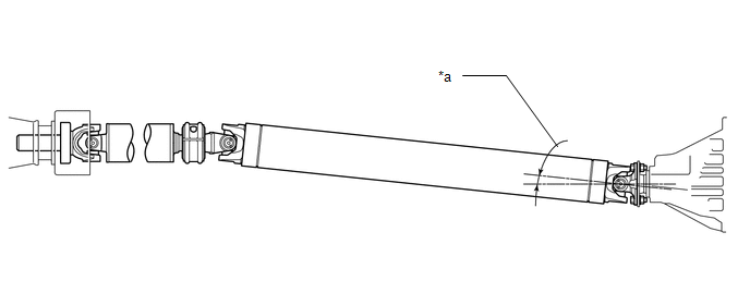
(b) Measure the No. 2 joint angle. (1) Using SST, measure and record the angle of the propeller shaft (D).
SST: 09370-50010 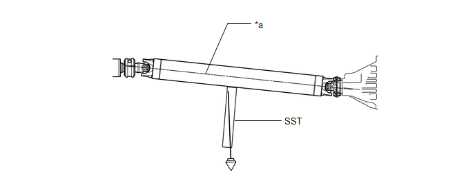 Text in Illustration Text in Illustration |
*a | Propeller Shaft Angle: D |
- | - |
(2)
Subtract the angle of the propeller shaft (D) from the angle of the
intermediate shaft (C) to calculate the No. 2 joint angle.
 Text in Illustration Text in Illustration
No. 2 joint angle: Angle of intermediate shaft (C) - Angle of propeller shaft (D)
Measured Value (Reference): |
Intermediate Shaft Angle Measured Value (C) |
Propeller Shaft Angle Measured Value (D) |
No. 2 Joint Angle (Calculated Value) (C) - (D) | |
3°15' (3.25°) | 5°30' (5.50°) |
-2°15' (-2.25°) |
HINT:
- Using the following chart, check if the calculated No. 2 joint angle is within the specified value.
- The tolerance is +/-0°60' (1.00°).
Standard No. 2 Joint Angle: |
Vehicle Model | No. 2 Joint Angle | |
UPK51L-CRTSKA | -2°14' +/-0°60' (-2.23° +/-1.00°) | |
UPK51L-PSTSKA | -1°04' +/-0°60' (-2.07° +/-1.00°) | |
USK51L-CRTLKA | -1°55' +/-0°60' (-1.92° +/-1.00°) | |
USK51L-CRTLKA*1 | -1°34' +/-0°60' (-1.56° +/-1.00°) | |
USK51L-CRTSKA | -1°55' +/-0°60' (-1.92° +/-1.00°) | |
USK51L-CRTSKA*1 | -1°37' +/-0°60' (-1.61° +/-1.00°) | |
USK51L-CRTSKA*2 | -1°55' +/-0°60' (-1.92° +/-1.00°) | |
USK51L-CRTSKA*3 | -1°55' +/-0°60' (-1.92° +/-1.00°) | |
USK51L-PSTLKA | -2°11' +/-0°60' (-2.18° +/-1.00°) | |
USK51L-PSTLKA*1 | -1°55' +/-0°60' (-1.92° +/-1.00°) | |
USK51L-PSTSKA | -2°11' +/-0°60' (-2.18° +/-1.00°) | |
USK51L-PSTSKA*1 | -1°58' +/-0°60' (-1.97° +/-1.00°) | |
USK51L-PSTSKA*2 | -2°11' +/-0°60' (-2.18° +/-1.00°) | |
USK51L-PSTZKA | -2°11' +/-0°60' (-2.19° +/-1.00°) | |
USK51L-PSTZKA*1 | -1°55' +/-0°60' (-1.92° +/-1.00°) | |
USK52L-CHTSKA | -1°07' +/-0°60' (-1.11° +/-1.00°) | |
USK52L-CHTSKA*1 | -0°48' +/-0°60' (-0.80° +/-1.00°) |
*1: includes Off road package *2: includes Sports package *3: includes YOUTH Edition package
- If the measured angle is not within the specification, adjust it with the bearing washer (See "Adjust Propeller Shaft Angle").
(c) Measure the No. 3 joint angle. (1)
Subtract the angle of the rear differential flange (B) measured before
installing the propeller shaft from the angle of the propeller shaft (D)
to calculate the No. 3 joint angle.
 Text in Illustration Text in Illustration
No. 3 joint angle: Angle of propeller shaft (D) - Angle of rear differential flange (B)
Measured Value (Reference): |
Propeller Shaft Angle Measured Value (D) |
Rear Differential Flange Angle Measured Value (B) |
No. 3 Joint Angle (Calculated Value) (D) - (B) | |
5°30' (5.50°) | 1°15' (1.25°) |
4°15' (4.25°) |
HINT:
- Using the following chart, check if the calculated No. 3 joint angle is within the specified value.
- The tolerance is +/-0°60' (1.00°).
Standard No. 3 Joint Angle: |
Vehicle Model | No. 3 Joint Angle | |
UPK51L-CRTSKA | 3°30' +/-0°60' (3.50° +/-1.00°) | |
UPK51L-PSTSKA | 3°52' +/-0°60' (3.87° +/-1.00°) | |
USK51L-CRTLKA | 2°43' +/-0°60' (2.71° +/-1.00°) | |
USK51L-CRTLKA*1 | 2°22' +/-0°60' (2.36° +/-1.00°) | |
USK51L-CRTSKA | 2°43' +/-0°60' (2.71° +/-1.00°) | |
USK51L-CRTSKA*1 | 2°24' +/-0°60' (2.40° +/-1.00°) | |
USK51L-CRTSKA*2 | 2°43' +/-0°60' (2.71° +/-1.00°) | |
USK51L-CRTSKA*3 | 2°43' +/-0°60' (2.71° +/-1.00°) | |
USK51L-PSTLKA | 3°58' +/-0°60' (3.97° +/-1.00°) | |
USK51L-PSTLKA*1 | 3°43' +/-0°60' (3.72° +/-1.00°) | |
USK51L-PSTSKA | 3°58' +/-0°60' (3.97° +/-1.00°) | |
USK51L-PSTSKA*1 | 3°46' +/-0°60' (3.77° +/-1.00°) | |
USK51L-PSTSKA*2 | 3°58' +/-0°60' (3.97° +/-1.00°) | |
USK51L-PSTZKA | 3°59' +/-0°60' (3.98° +/-1.00°) | |
USK51L-PSTZKA*1 | 3°00' +/-0°60' (3.72° +/-1.00°) | |
USK52L-CHTSKA | 3°07' +/-0°60' (3.12° +/-1.00°) | |
USK52L-CHTSKA*1 | 2°50' +/-0°60' (2.83° +/-1.00°) |
*1: includes Off road package *2: includes Sports package *3: includes YOUTH Edition package
- If the measured angle is not within the specification, adjust it with the bearing washer (See "Adjust Propeller Shaft Angle").
5. ADJUST PROPELLER SHAFT ANGLE HINT: If
the propeller shaft angle is outside the specification or there is
vibration and noise, perform the propeller shaft adjustment using the
following procedure. (a) Adjust the No. 1, No. 2 and No. 3 joint angle.
(1) Support the propeller shaft with a jack. (2) Remove the 2 center bearing mounting bolts.
(3) Slowly lower the jack, and disconnect the center bearing. (4) Select an appropriate center support bearing washer thickness from the table below, and obtain a washer set.
Standard Bearing Washer Thickness: |
Thickness | | 2.0 mm (0.0787 in.) | |
4.5 mm (0.1772 in.) | |
6.5 mm (0.2559 in.) | |
9.0 mm (0.3543 in.) | |
11.0 mm (0.4331 in.) | |
13.5 mm (0.5315 in.) |
HINT:
6. INSPECT FOR OIL LEAK |