DISASSEMBLY PROCEDURE 1. REMOVE REAR PROPELLER SHAFT UNIVERSAL JOINT SPIDER BEARING
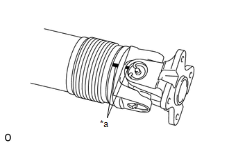
 (a) Place matchmarks on the propeller shaft yoke and universal joint yoke. Text in Illustration
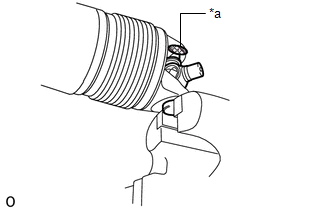
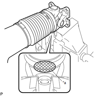
| (b) Remove the grease fitting from the spider bearing. |
|
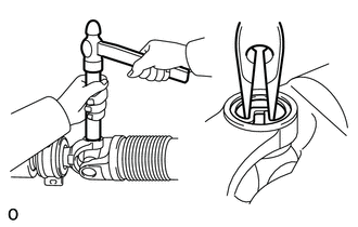
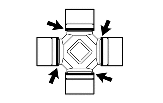
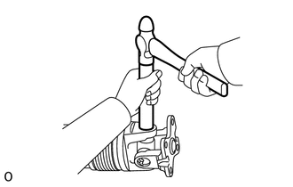
| (c) Using a brass bar and hammer, slightly tap in the 4 spider bearings. |
|
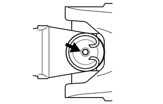
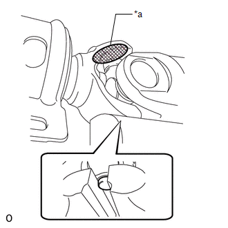
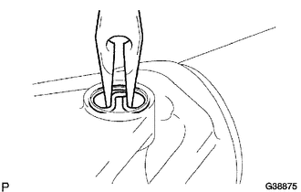
(d) Using needle-nose pliers, remove the 4 snap rings from the grooves.
| (e) Using a screwdriver, remove the 4 slingers of the spider bearing. |
|
(f) Clamp the propeller shaft in a vise between aluminum plates.
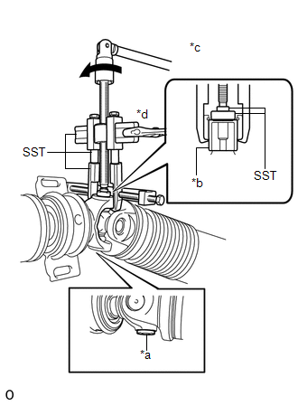
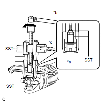
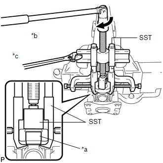
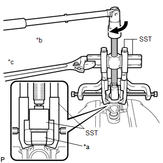
| (g) Using SST, press in spider bearing B until spider bearing A can be clamped in a vise.
SST: 09950-40011 09951-04010 09952-04010 09953-04030
09954-04010 09957-04010 09958-04011 SST: 09950-60010
09951-00290 SST: 09955-04100 Text in Illustration |
*a | Spider Bearing A | |
*b | Spider Bearing B | |
*c | Turn | |
*d | Hold |
HINT: Make sure the claws of SST are securely attached to the universal joint yoke. |
|
(h) Clamp the protruding universal joint spider bearing in a vise.
| (i) Using a brass bar and hammer, tap the universal joint yoke to remove the universal joint spider bearing. Text in Illustration
NOTICE: Do not tap the intermediate shaft tube. HINT:
Use the same removal procedure for the universal joint spider bearing on the opposite side. |
|
(j) Disconnect the intermediate shaft from the propeller shaft.
| (k) Using SST, pull out the universal joint spider bearing from the propeller shaft yoke.
SST: 09331-60010 SST: 09950-40011 09951-04010 09952-04010
09953-04020 09954-04010 09957-04010 09958-04011
SST: 09955-04100 Text in Illustration |
*a | Spider Bearing | |
*b | Turn | |
*c | Hold |
NOTICE: Pull out the spider bearing until the SST claws contact the propeller shaft yoke. |
|
(l) Clamp the protruding universal joint spider bearing in a vise.
| (m) Using a brass bar and hammer, tap the propeller shaft yoke to remove the universal joint spider bearing. Text in Illustration
NOTICE: Do not tap the propeller shaft tube. HINT: Use the same removal procedure for the universal joint spider bearing on the opposite side. |
|
(n) Remove the spider from the propeller shaft. 2. REMOVE NO. 1 CENTER SUPPORT BEARING ASSEMBLY
(a) Fix the center support bearing in a vise. (b) Using a chisel and hammer, loosen the staked part of the lock nut. Then remove the lock nut.
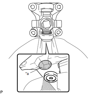
| (c) Place matchmarks on the joint yoke and shaft. Text in Illustration |
|
(d)
Using a brass bar and hammer, tap the end of the intermediate shaft to
remove the joint yoke, washer and center support bearing from the
intermediate shaft. 3. REMOVE REAR PROPELLER SHAFT UNIVERSAL JOINT SPIDER BEARING
HINT: Use the same removal procedure for both the front and rear propeller shaft universal joint spider bearings.
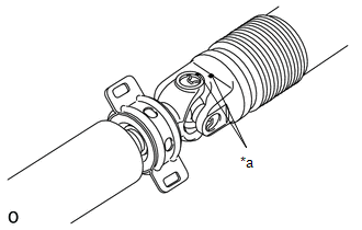
| (a) Place matchmarks on the flange yoke and shaft. Text in Illustration |
|
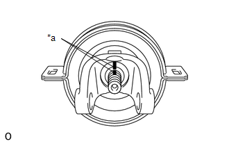
(b) Remove the grease fitting from the spider bearing.
| (c) Using a brass bar and hammer, slightly tap in the 4 spider bearings. |
|
| (d) Using needle-nose pliers, remove the 4 snap rings from the grooves. |
|
| (e) Using a screwdriver, remove the 4 slingers of the spider bearing. |
|
(f) Clamp the shaft in a vise between aluminum plates.
| (g) Using SST, pull out the universal joint spider bearing from the shaft.
SST: 09331-60010 SST: 09950-40011 09951-04010 09952-04010
09953-04020 09954-04010 09957-04010 09958-04011
SST: 09955-04100 Text in Illustration |
*a | Spider Bearing | |
*b | Turn | |
*c | Hold |
NOTICE: Pull out the spider bearing until the SST claws contact the shaft's universal joint yoke. |
|
(h) Clamp the protruding universal joint spider bearing in a vise.
| (i) Using a brass bar and hammer, tap the shaft yoke to remove the universal joint spider bearing. Text in Illustration
NOTICE: Do not tap the shaft tube. HINT: Use the same removal procedure for the universal joint spider bearing on the opposite side. |
|
| (j) Using SST, pull out the universal joint spider bearing from the flange yoke.
SST: 09331-60010 SST: 09950-40011 09951-04010 09952-04010
09953-04020 09954-04010 09957-04010 09958-04011
SST: 09955-04100 Text in Illustration |
*a | Spider Bearing | |
*b | Turn | |
*c | Hold |
NOTICE: Pull out the spider bearing until the SST claws contact the flange yoke. |
|
(k) Clamp the protruding universal joint spider bearing in a vise.
| (l) Using a brass bar and hammer, tap the flange yoke to remove the universal joint spider bearing. Text in Illustration
HINT: Use the same removal procedure for the universal joint spider bearing on the opposite side. |
|
(m) Remove the spider from the flange yoke. |