Toyota Tundra Service Manual: Installation

INSTALLATION

PROCEDURE

1. MEASURE TRANSFER AND DIFFERENTIAL FLANGE ANGLE

NOTICE:

  • Perform the inspection on a level surface.
  • Perform the inspection with the vehicle empty.
  • Perform the inspection with all wheels on the ground.

HINT:

As the transfer and rear differential flange angles are necessary when measuring the installation angle of the propeller shaft, measure the angle of the transfer and rear differential flange before installing the propeller shaft.

(a) Using SST, measure and record the angle of the transfer flange (A).

SST: 09370-50010

Text in Illustration

*a

Transfer Flange Angle: A

(b) Using SST, measure and record the angle of the rear differential flange (B).

SST: 09370-50010

Text in Illustration

*a

Rear Differential Flange Angle: B

2. TEMPORARILY INSTALL PROPELLER WITH CENTER BEARING SHAFT ASSEMBLY

(a) Completely remove any oil or the like and clean the contact surfaces of the propeller shaft flange, transfer flange and differential flange.

(b) w/o Bearing Washer:

(1) Temporarily install the center support bearing to the crossmember with the 2 mounting bolts.

(c) w/ Bearing Washer:

(1) Temporarily install the center support bearing to the crossmember with the 2 bearing washers and 2 mounting bolts.

Text in Illustration

*1

No. 2 Center Support Bearing Washer

*2

No. 1 Center Support Bearing Assembly

*a

Frame

(d) Align the matchmarks on the flange yoke and transfer flange.

Text in Illustration

*a

for Transfer Side

*b

Matchmark

(e) Install the propeller shaft to the transfer side with the 4 nuts.

Torque:

70 N·m {714 kgf·cm, 52 ft·lbf}

(f) Align the matchmarks on the flange yoke and differential flange.

Text in Illustration

*a

for Differential Side

*b

Matchmark

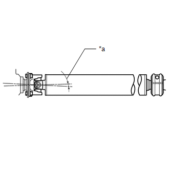
(g) Install the propeller shaft to the differential side with the 4 bolts and 4 nuts.

Torque:

70 N·m {714 kgf·cm, 52 ft·lbf}

3. TIGHTEN PROPELLER WITH CENTER BEARING SHAFT ASSEMBLY

(a) With the vehicle empty and all 4 tires supported by a lift, or with the vehicle suspension in the full rebound position, adjust the center bearing so that dimension A (the distance from the front surface of the center bearing housing to the back surface of the intermediate shaft) is as shown in the chart below.

HINT:

Measure dimension A (the distance from the front surface of the center bearing housing to the back surface of the intermediate shaft) at 3 places and make adjustments so that the measured dimensions are equal.
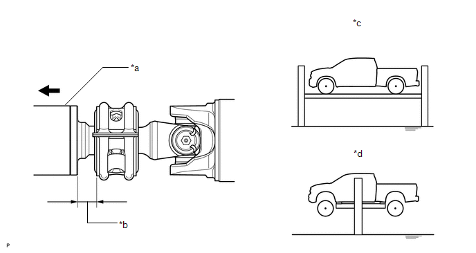
Text in Illustration

*a

Intermediate Shaft

*b

Dimension A

*c

Tires supported and vehicle empty (When using drive-on type lift)

*d

Full rebound position (When using 2 post lift)

Front Side

-

-

Standard Dimension A:

Vehicle Model

Vehicle Condition

Dimension A

All Model

Tires supported and vehicle empty (When using drive-on type lift)

26.0 mm (1.024 in.)

Full rebound position (When using 2 post lift)

26.0 mm (1.024 in.)

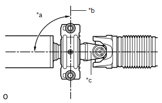
(b) Check that the center line of the bracket is at right angles to the shaft axial direction.

(c) Tighten the 2 mounting bolts.

Torque:

40 N·m {410 kgf·cm, 30 ft·lbf}

Text in Illustration

*a

90°

*b

Bracket Center Line

*c

Shaft Axial Direction

4. INSPECT PROPELLER SHAFT JOINT ANGLE

NOTICE:

  • Perform the inspection on a level surface.
  • Perform the inspection with the vehicle empty.
  • Perform the inspection with all wheels on the ground.

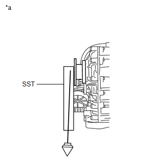
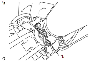
(a) Measure the No. 1 joint angle.

(1) Using SST, measure and record the angle of the intermediate shaft (C).

SST: 09370-50010
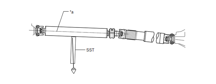
Text in Illustration

*a

Intermediate Shaft Angle: C

-

-

(2) Subtract the angle of the transfer flange (A) measured before installing the propeller shaft from the angle of the intermediate shaft (C) to calculate the No. 1 joint angle.

Text in Illustration

*a

No. 1 Joint Angle

No. 1 joint angle:

Angle of intermediate shaft (C) - Angle of transfer flange (A)

Measured Value (Reference):

Intermediate Shaft Angle Measured Value (C)

Transfer Flange Angle Measured Value (A)

No. 1 Joint Angle (Calculated Value)

(C) - (A)

2°30' (2.50°)

3°45' (3.75°)

-1°15' (-1.25°)

HINT:

  • Using the following chart, check if the calculated No. 1 joint angle is within the specified value.
  • The tolerance is +/-0°60' (1.00°).

    Standard No. 1 Joint Angle:

    Vehicle Model

    No. 1 Joint Angle

    UPK56L-CRTSKA

    0°52' +/-0°60' (0.87° +/-1.00°)

    UPK56L-PSTSKA

    0°52' +/-0°60' (0.87° +/-1.00°)

    USK56L-CRTLGA

    0°52' +/-0°60' (0.87° +/-1.00°)

    USK56L-CRTLGA*1

    USK56L-CRTLKA

    0°52' +/-0°60' (0.87° +/-1.00°)

    USK56L-CRTLKA*1

    USK56L-CRTSGA

    0°52' +/-0°60' (0.87° +/-1.00°)

    USK56L-CRTSGA*1

    USK56L-CRTSGA*2

    USK56L-CRTSGA*3

    0°52' +/-0°60' (0.87° +/-1.00°)

    USK56L-CRTSGA*4

    0°52' +/-0°60' (0.87° +/-1.00°)

    USK56L-CRTSKA

    0°52' +/-0°60' (0.87° +/-1.00°)

    USK56L-CRTSKA*1

    USK56L-CRTSKA*2

    USK56L-CRTSKA*3

    0°52' +/-0°60' (0.87° +/-1.00°)

    USK56L-CRTSKA*4

    0°52' +/-0°60' (0.87° +/-1.00°)

    USK56L-PSTLGA

    0°52' +/-0°60' (0.87° +/-1.00°)

    USK56L-PSTLGA*1

    USK56L-PSTLKA

    0°52' +/-0°60' (0.87° +/-1.00°)

    USK56L-PSTLKA*1

    USK56L-PSTSGA

    0°52' +/-0°60' (0.87° +/-1.00°)

    USK56L-PSTSGA*1

    USK56L-PSTSGA*2

    USK56L-PSTSGA*3

    0°52' +/-0°60' (0.87° +/-1.00°)

    USK56L-PSTSKA

    0°52' +/-0°60' (0.87° +/-1.00°)

    USK56L-PSTSKA*1

    USK56L-PSTSKA*2

    USK56L-PSTSKA*3

    0°52' +/-0°60' (0.87° +/-1.00°)

    USK56L-PSTZGA

    0°52' +/-0°60' (0.87° +/-1.00°)

    USK56L-PSTZGA*1

    0°52' +/-0°60' (0.87° +/-1.00°)

    USK56L-PSTZKA

    0°52' +/-0°60' (0.87° +/-1.00°)

    USK56L-PSTZKA*1

    0°52' +/-0°60' (0.87° +/-1.00°)

    USK57L-CHTSGA

    1°07' +/-0°60' (1.12° +/-1.00°)

    USK57L-CHTSGA*1

    USK57L-CHTSKA

    1°07' +/-0°60' (1.12° +/-1.00°)

    USK57L-CHTSKA*1

HINT:

*1: includes Off road package

*2: includes Off road pro package

*3: includes Sports package

*4: includes YOUTH Edition package

  • If the measured angle is not within the specification, adjust it with the bearing washer (See "Adjust Propeller Shaft Angle").

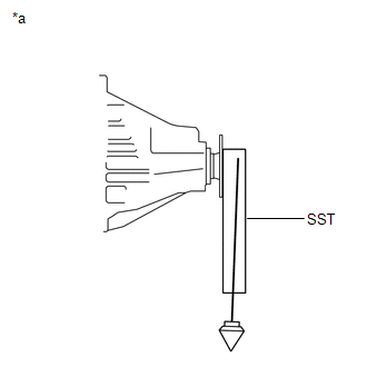
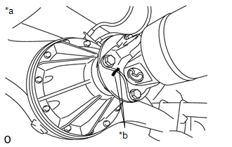
(b) Measure the No. 2 joint angle.

(1) Using SST, measure and record the angle of the propeller shaft (D).

SST: 09370-50010
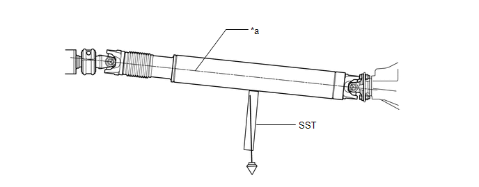
Text in Illustration

*a

Propeller Shaft Angle: D

-

-

(2) Subtract the angle of the propeller shaft (D) from the angle of the intermediate shaft (C) to calculate the No. 2 joint angle.
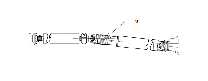
Text in Illustration

*a

No. 2 Joint Angle

-

-

No. 2 joint angle:

Angle of intermediate shaft (C) - Angle of propeller shaft (D)

Measured Value (Reference):

Intermediate Shaft Angle Measured Value (C)

Propeller Shaft Angle Measured Value (D)

No. 2 Joint Angle (Calculated Value)

(C) - (D)

2°30' (2.50°)

5°45' (5.75°)

-3°15' (-3.25°)

HINT:

  • Using the following chart, check if the calculated No. 2 joint angle is within the specified value.
  • The tolerance is +/-0°60' (1.00°).

    Standard No. 2 Joint Angle:

    Vehicle Model

    No. 2 Joint Angle

    UPK56L-CRTSKA

    -2°53' +/-0°60' (-2.89° +/-1.00°)

    UPK56L-PSTSKA

    -2°25' +/-0°60' (-2.42° +/-1.00°)

    USK56L-CRTLGA

    -2°10' +/-0°60' (-2.17° +/-1.00°)

    USK56L-CRTLGA*1

    -2°07' +/-0°60' (-2.12° +/-1.00°)

    USK56L-CRTLKA

    -2°10' +/-0°60' (-2.17° +/-1.00°)

    USK56L-CRTLKA*1

    -2°07' +/-0°60' (-2.12° +/-1.00°)

    USK56L-CRTSGA

    -2°13' +/-0°60' (-2.22° +/-1.00°)

    USK56L-CRTSGA*1

    -2°13' +/-0°60' (-2.22° +/-1.00°)

    USK56L-CRTSGA*2

    -2°13' +/-0°60' (-2.22° +/-1.00°)

    USK56L-CRTSGA*3

    -2°13' +/-0°60' (-2.22° +/-1.00°)

    USK56L-CRTSGA*4

    -2°13' +/-0°60' (-2.22° +/-1.00°)

    USK56L-CRTSKA

    -2°13' +/-0°60' (-2.22° +/-1.00°)

    USK56L-CRTSKA*1

    -2°13' +/-0°60' (-2.22° +/-1.00°)

    USK56L-CRTSKA*2

    -2°13' +/-0°60' (-2.22° +/-1.00°)

    USK56L-CRTSKA*3

    -2°13' +/-0°60' (-2.22° +/-1.00°)

    USK56L-CRTSKA*4

    -2°13' +/-0°60' (-2.22° +/-1.00°)

    USK56L-PSTLGA

    -2°23' +/-0°60' (-2.38° +/-1.00°)

    USK56L-PSTLGA*1

    -2°20' +/-0°60' (-2.33° +/-1.00°)

    USK56L-PSTLKA

    -2°23' +/-0°60' (-2.38° +/-1.00°)

    USK56L-PSTLKA*1

    -2°20' +/-0°60' (-2.33° +/-1.00°)

    USK56L-PSTSGA

    -2°26' +/-0°60' (-2.43° +/-1.00°)

    USK56L-PSTSGA*1

    -2°20' +/-0°60' (-2.33° +/-1.00°)

    USK56L-PSTSGA*2

    -2°20' +/-0°60' (-2.33° +/-1.00°)

    USK56L-PSTSGA*3

    -2°13' +/-0°60' (-2.22° +/-1.00°)

    USK56L-PSTSKA

    -2°26' +/-0°60' (-2.43° +/-1.00°)

    USK56L-PSTSKA*1

    -2°20' +/-0°60' (-2.33° +/-1.00°)

    USK56L-PSTSKA*2

    -2°20' +/-0°60' (-2.33° +/-1.00°)

    USK56L-PSTSKA*3

    -2°13' +/-0°60' (-2.22° +/-1.00°)

    USK56L-PSTZGA

    -2°23' +/-0°60' (-2.38° +/-1.00°)

    USK56L-PSTZGA*1

    -2°23' +/-0°60' (-2.38° +/-1.00°)

    USK56L-PSTZKA

    -2°23' +/-0°60' (-2.38° +/-1.00°)

    USK56L-PSTZKA*1

    -2°23' +/-0°60' (-2.38° +/-1.00°)

    USK57L-CHTSGA

    -1°26' +/-0°60' (-1.44° +/-1.00°)

    USK57L-CHTSGA*1

    -1°26' +/-0°60' (-1.44° +/-1.00°)

    USK57L-CHTSKA

    -1°26' +/-0°60' (-1.44° +/-1.00°)

    USK57L-CHTSKA*1

    -1°26' +/-0°60' (-1.44° +/-1.00°)

HINT:

*1: includes Off road package

*2: includes Off road pro package

*3: includes Sports package

*4: includes YOUTH Edition package

  • If the measured angle is not within the specification, adjust it with the bearing washer (See "Adjust Propeller Shaft Angle").

(c) Measure the No. 3 joint angle.

(1) Subtract the angle of the rear differential flange (B) measured before installing the propeller shaft from the angle of the propeller shaft (D) to calculate the No. 3 joint angle.
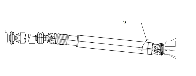
Text in Illustration

*a

No. 3 Joint Angle

-

-

No. 3 joint angle:

Angle of propeller shaft (D) - Angle of rear differential flange (B)

Measured Value (Reference):

Propeller Shaft Angle Measured Value (D)

Rear Differential Flange Angle Measured Value (B)

No. 3 Joint Angle (Calculated Value)

(D) - (B)

5°45' (5.75°)

2°30' (2.50°)

3°15' (3.25°)

HINT:

  • Using the following chart, check if the calculated No. 3 joint angle is within the specified value.
  • The tolerance is +/-0°60' (1.00°).

    Standard No. 3 Joint Angle:

    Vehicle Model

    No. 3 Joint Angle

    UPK56L-CRTSKA

    3°58' +/-0°60' (3.96° +/-1.00°)

    UPK56L-PSTSKA

    4°01' +/-0°60' (4.02° +/-1.00°)

    USK56L-CRTLGA

    2°47' +/-0°60' (2.78° +/-1.00°)

    USK56L-CRTLGA*1

    2°43' +/-0°60' (2.72° +/-1.00°)

    USK56L-CRTLKA

    2°47' +/-0°60' (2.78° +/-1.00°)

    USK56L-CRTLKA*1

    2°43' +/-0°60' (2.72° +/-1.00°)

    USK56L-CRTSGA

    2°50' +/-0°60' (2.83° +/-1.00°)

    USK56L-CRTSGA*1

    2°50' +/-0°60' (2.83° +/-1.00°)

    USK56L-CRTSGA*2

    2°50' +/-0°60' (2.83° +/-1.00°)

    USK56L-CRTSGA*3

    2°50' +/-0°60' (2.83° +/-1.00°)

    USK56L-CRTSGA*4

    2°50' +/-0°60' (2.83° +/-1.00°)

    USK56L-CRTSKA

    2°50' +/-0°60' (2.83° +/-1.00°)

    USK56L-CRTSKA*1

    2°50' +/-0°60' (2.83° +/-1.00°)

    USK56L-CRTSKA*2

    2°50' +/-0°60' (2.83° +/-1.00°)

    USK56L-CRTSKA*3

    2°50' +/-0°60' (2.83° +/-1.00°)

    USK56L-CRTSKA*4

    2°50' +/-0°60' (2.83° +/-1.00°)

    USK56L-PSTLGA

    3°29' +/-0°60' (3.48° +/-1.00°)

    USK56L-PSTLGA*1

    3°26' +/-0°60' (3.43° +/-1.00°)

    USK56L-PSTLKA

    3°29' +/-0°60' (3.48° +/-1.00°)

    USK56L-PSTLKA*1

    3°26' +/-0°60' (3.43° +/-1.00°)

    USK56L-PSTSGA

    3°32' +/-0°60' (3.54° +/-1.00°)

    USK56L-PSTSGA*1

    3°26' +/-0°60' (3.43° +/-1.00°)

    USK56L-PSTSGA*2

    3°26' +/-0°60' (3.43° +/-1.00°)

    USK56L-PSTSGA*3

    3°32' +/-0°60' (3.54° +/-1.00°)

    USK56L-PSTSKA

    3°32' +/-0°60' (3.54° +/-1.00°)

    USK56L-PSTSKA*1

    3°26' +/-0°60' (3.43° +/-1.00°)

    USK56L-PSTSKA*2

    3°26' +/-0°60' (3.43° +/-1.00°)

    USK56L-PSTSKA*3

    3°32' +/-0°60' (3.54° +/-1.00°)

    USK56L-PSTZGA

    3°29' +/-0°60' (3.48° +/-1.00°)

    USK56L-PSTZGA*1

    3°29' +/-0°60' (3.48° +/-1.00°)

    USK56L-PSTZKA

    3°29' +/-0°60' (3.48° +/-1.00°)

    USK56L-PSTZKA*1

    3°29' +/-0°60' (3.48° +/-1.00°)

    USK57L-CHTSGA

    3°17' +/-0°60' (3.29° +/-1.00°)

    USK57L-CHTSGA*1

    3°17' +/-0°60' (3.29° +/-1.00°)

    USK57L-CHTSKA

    3°17' +/-0°60' (3.29° +/-1.00°)

    USK57L-CHTSKA*1

    3°17' +/-0°60' (3.29° +/-1.00°)

HINT:

*1: includes Off road package

*2: includes Off road pro package

*3: includes Sports package

*4: includes YOUTH Edition package

  • If the measured angle is not within the specification, adjust it with the bearing washer (See "Adjust Propeller Shaft Angle").

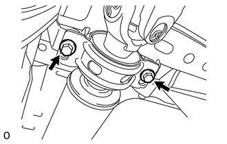
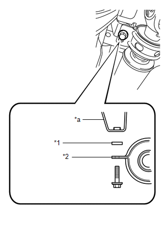
5. ADJUST PROPELLER SHAFT ANGLE

HINT:

If the propeller shaft angle is outside the specification or there is vibration and noise, perform the propeller shaft adjustment using the following procedure.

(a) Adjust the No. 1, No. 2 and No. 3 joint angle.

(1) Support the propeller shaft with a jack.

(2) Remove the 2 center bearing mounting bolts.

(3) Slowly lower the jack, and disconnect the center bearing.

(4) Select an appropriate center support bearing washer thickness from the table below, and obtain a washer set.

Standard Bearing Washer Thickness:

Thickness

2.0 mm (0.0787 in.)

4.5 mm (0.1772 in.)

6.5 mm (0.2559 in.)

9.0 mm (0.3543 in.)

11.0 mm (0.4331 in.)

13.5 mm (0.5315 in.)

HINT:

  • Each set contains 2 washers.
  • Using the washer set, perform the adjustment.
  • As a reference when selecting a bearing washer, the angle changes as follows for every 1.0 mm (0.0394 in.) change in bearing washer thickness.

    Angle variation for every 1.0 mm (0.0394 in.) change in bearing washer thickness:

    No. 1 joint angle

    0°04' (0.06°)

    No. 2 joint angle

    0°07' (0.12°)

    No. 3 joint angle

    0°04' (0.06°)

    Inspection

    Reassembly

    See More:

    Toyota Tundra Service Manual > Audio And Visual System: Sound of Portable Player cannot be Heard from Speakers or Sound is Low
    PROCEDURE 1. CHECK PORTABLE PLAYER SETTINGS (a) Check the portable player settings. (1) Check that the volume is not set to "0". (2) Check that mute is off. (b) Check that the sound of the portable player can be heard from the speakers. OK: Sound of the portable player can be heard from the speakers ...

    Toyota Tundra Owners Manual

    Toyota Tundra Service Manual

    © 2024 Copyright www.ttundra.com
    0.034