REMOVAL PROCEDURE 1. REMOVE PROPELLER WITH CENTER BEARING SHAFT ASSEMBLY 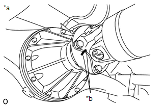 (a) Place matchmarks on the propeller shaft flange and differential flange. Text in Illustration
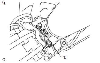
(b) Remove the 4 bolts and 4 nuts.
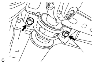
(d) w/ Bearing Washer: (1) Remove the 2 mounting bolts and 2 bearing washers from the frame crossmember.
(f) Remove the 4 nuts and propeller shaft. |
Toyota Tundra Service Manual > Camshaft(for Bank 1): Installation
INSTALLATION CAUTION / NOTICE / HINT HINT: Perform " Inspection After Repairs" after replacing the No. 3 or No. 4 camshaft or camshaft timing gear LH or camshaft timing exhaust gear LH (See page ). PROCEDURE 1. INSTALL CAMSHAFT BEARING CAP LH HINT: Perform "Inspection After Repairs" after replacing ...