REMOVAL CAUTION / NOTICE / HINT HINT:
PROCEDURE 1. REMOVE FRONT WHEEL 2. REMOVE FRONT STABILIZER LINK ASSEMBLY LH 3. DISCONNECT FRONT SHOCK ABSORBER WITH COIL SPRING LH 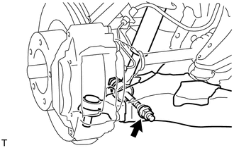 (a) Remove the nut and bolt, and disconnect the shock absorber from the lower side. 4. DISCONNECT FRONT LOWER BALL JOINT ATTACHMENT LH 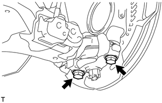 (a) Remove the 2 bolts and disconnect the attachment from the steering knuckle. 5. REMOVE FRONT NO. 1 SUSPENSION ARM SUB-ASSEMBLY LOWER LH 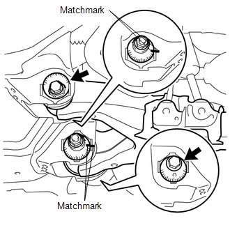 (a) Place matchmarks on the No. 2 camber adjusting cam and No. 2 toe adjusting plate. (b) Remove the nut, washer, No. 2 camber adjusting cam, camber adjusting cam assembly, bolt, toe adjusting cam, No. 2 toe adjusting plate and front No. 1 suspension arm lower LH. 6. REMOVE FRONT LOWER BALL JOINT ATTACHMENT LH (a) Remove the cotter pin and nut. (b) Using SST, remove the lower ball joint attachment. 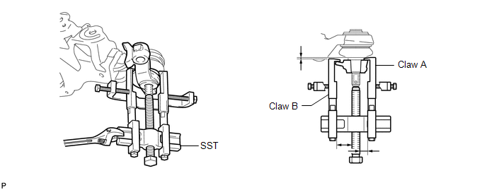 SST: 09950-40011 09951-04010 09953-04020 09954-04010 09955-04031 09958-04011 09952-04010 SST: 09955-04090 HINT: Claw A 09955-04090 Claw B 09955-04031 |
Toyota Tundra Owners Manual > Toyota Tundra Owners Manual: Pictorial index
Exterior Side doors Locking/unlocking Opening/closing the door glasses Warning messages Tailgate Locking/unlocking Opening/closing the tailgate Removing the tailgate Outside rear view mirrors Adjusting the mirror angle Folding the mirrors Driving position memory*1 Defogging the mirrors*2 Windshield ...


