Toyota Tundra Service Manual: Installation

INSTALLATION

CAUTION / NOTICE / HINT

HINT:

  • Use the same procedures for the RH side and LH side.
  • The procedures listed below are for the LH side.
  • A bolt without a torque specification is shown in the standard bolt chart (see page ).

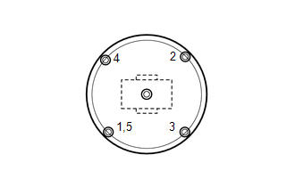
PROCEDURE

1. TEMPORARILY INSTALL FRONT SHOCK ABSORBER WITH COIL SPRING

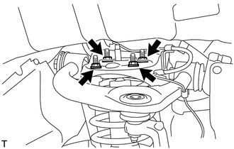
(a) Temporarily install the upper side of the shock absorber to the chassis frame with the 4 nuts.

(b) Temporarily install the lower side of the shock absorber to the lower suspension arm with the bolt, washer and nut.

2. STABILIZE SUSPENSION

(a) Lower the vehicle.

(b) Press down on the vehicle several times to stabilize the suspension.

3. TIGHTEN FRONT SHOCK ABSORBER WITH COIL SPRING

(a) Tighten the nut.

Torque:

195 N·m {1988 kgf·cm, 144 ft·lbf}

(b) Tighten the 4 upper nuts in diametrically opposite pairs.

Torque:

45 N·m {459 kgf·cm, 33 ft·lbf}

(c) Check that the first nut that was tightened is at the torque specification.

4. INSTALL FRONT WHEEL

Torque:

for Aluminum Wheel :

131 N·m {1336 kgf·cm, 97 ft·lbf}

for Steel Wheel :

209 N·m {2131 kgf·cm, 154 ft·lbf}

    Inspection

    Reassembly

    See More:

    Toyota Tundra Service Manual > Intuitive Parking Assist System: Clearance Warning ECU Power Source Circuit
    DESCRIPTION This circuit is the power source circuit to operate the clearance warning ECU assembly. WIRING DIAGRAM CAUTION / NOTICE / HINT NOTICE: Inspect the fuses for circuits related to this system before performing the following procedure. PROCEDURE 1. CHECK HARNESS AND CONNECTOR (BACK SONAR OR ...

    Toyota Tundra Owners Manual

    Toyota Tundra Service Manual

    © 2026 Copyright www.ttundra.com
    0.0113