DESCRIPTION After the tire
pressure warning valve and transmitter ID registration is completed
using the Techstream or ID registration was canceled via the automatic
ID registration function, DTC C2126/26 is output from the tire pressure
warning ECU and receiver. After ID registration
is complete using the Techstream, the tire pressure warning light
illuminates after blinking for 1 minute. When the tire pressure warning
ECU and receiver receives the data from all tire pressure warning valve
and transmitters with registered IDs, the tire pressure is judged to be
normal and the tire pressure warning light turns off. |
DTC No. | Detection Item |
DTC Detection Condition | Trouble Area |
Note | | C2126/26 |
Transmitter ID not Received in Main Mode |
- After transmitter ID registration is completed, ECU does not receive radio waves from transmitters whose IDs are stored in ECU.
- When the ID registration operation is canceled via the automatic ID registration function
|
- Transmitter ID registration failure
- Tire pressure warning valve and transmitter
- Tire pressure warning ECU and receiver
| - |
NOTICE: If
DTC C2126/26 is output, C2128/28 may be output simultaneously. In this
case, first perform troubleshooting for C2128/28 first and then perform
troubleshooting for C2126/26. HINT: The
purpose of this DTC is to help prevent delivering a vehicle that has
incorrectly registered transmitter IDs. After all IDs are registered,
DTC C2126/26 is detected and the tire pressure warning light blinks for 1
minute and then illuminates. If the tire pressure warning light does
not go off after a little while, the transmitter IDs may be incorrectly
registered. CAUTION / NOTICE / HINT
NOTICE:
- When replacing the tire pressure warning ECU and receiver, read the
transmitter IDs stored in the old ECU using the Techstream and write
them down before removal.
- It is necessary to perform initialization
 after registration
of the transmitter IDs into the tire pressure warning ECU and receiver
if the ECU and/or one of the valve and transmitters has been replaced. after registration
of the transmitter IDs into the tire pressure warning ECU and receiver
if the ECU and/or one of the valve and transmitters has been replaced.
PROCEDURE |
1. | IDENTIFY TRANSMITTER NOT RECEIVED |
(a) Set the tire pressure to the specified value. Click here
(b) Turn the ignition switch to ON and let the vehicle idle for 2 to 3 minutes.
HINT: For
this vehicle, it may take longer than usual to receive data from the
tire pressure warning valve and transmitter while the Data List is
displayed. Therefore, before displaying the Data List, wait 2 to 3
minutes to receive data from the tire pressure warning valve and
transmitter. (c) Turn the ignition switch off. (d) Connect the Techstream to the DLC3.
(e) Turn the ignition switch to ON. (f) Turn the Techstream on.
(g) Enter the following menus: Chassis / Tire Pressure Monitor / Data List.
(h) Display the "ID Tire Inflation Pressure" value for each wheel using the Techstream.
(i)
Rapidly reduce the tire pressure for each wheel at least 40 kPa (0.4
kg/cm2, 5.8 psi) within 30 seconds. If the "ID Tire Inflation Pressure"
value displayed on the Techstream does not change, the tire pressure
warning valve and transmitter corresponding to the unchanged "ID Tire
Inflation Pressure" value was the cause of the output DTC.
HINT:
- Identify the malfunctioning tire pressure warning valve and transmitter
by repeatedly decreasing the tire pressure for each tire.
- Record which "ID Tire Inflation Pressure" value corresponds to each tire.
Chassis > Tire Pressure Monitor > Data List |
Tester Display | Measurement Item |
Range | Normal Condition |
Diagnostic Note | |
ID 1 Tire Inflation Pressure |
ID1 tire inflation pressure |
min.: Absolute pressure (abs) / 0 kPa (0 kgf/cm2, 0 psi), Relative pressure (Gauge) / 0 kPa (0 kgf/cm2, 0 psi)
max.: Absolute pressure (abs) / 480 kPa (4.9 kgf/cm2, 70 psi), Relative pressure (Gauge) / 380 kPa (3.9 kgf/cm2, 55 psi) |
Actual tire inflation pressure |
If N/A is displayed, data has not been received.* | |
ID 2 Tire Inflation Pressure |
ID2 tire inflation pressure |
min.: Absolute pressure (abs) / 0 kPa (0 kgf/cm2, 0 psi), Relative pressure (Gauge) / 0 kPa (0 kgf/cm2, 0 psi)
max.: Absolute pressure (abs) / 480 kPa (4.9 kgf/cm2, 70 psi), Relative pressure (Gauge) / 380 kPa (3.9 kgf/cm2, 55 psi) |
Actual tire inflation pressure |
If N/A is displayed, data has not been received.* | |
ID 3 Tire Inflation Pressure |
ID3 tire inflation pressure |
min.: Absolute pressure (abs) / 0 kPa (0 kgf/cm2, 0 psi), Relative pressure (Gauge)/ 0 kPa (0 kgf/cm2, 0 psi)
max.: Absolute pressure (abs) / 480 kPa (4.9 kgf/cm2, 70 psi), Relative pressure (Gauge) / 380 kPa (3.9 kgf/cm2, 55 psi) |
Actual tire inflation pressure |
If N/A is displayed, data has not been received.* | |
ID 4 Tire Inflation Pressure |
ID4 tire inflation pressure |
min.: Absolute pressure (abs) / 0 kPa (0 kgf/cm2, 0 psi), Relative pressure (Gauge) / 0 kPa (0 kgf/cm2, 0 psi)
max.: Absolute pressure (abs) / 480 kPa (4.9 kgf/cm2, 70 psi), Relative pressure (Gauge) / 380 kPa (3.9 kgf/cm2, 55 psi) |
Actual tire inflation pressure |
If N/A is displayed, data has not been received.* |
HINT:
- *: It may take a few minutes until the values are displayed.
- The wheel position cannot be determined from ID1 through ID4 on the Data List.
(j) Check the Data List.
NOTICE:
- It may take a few minutes until the values are displayed.
- When an "ID Tire Inflation Pressure" value has not changed, reset the
tire pressure to the appropriate specified value and rotate the tire 90
to 270 degrees. Then rapidly release the tire pressure and recheck the
value.
(k) After confirming that the "ID
Tire Inflation Pressure" value for one tire has changed, repeat this
procedure for each tire. Identify the transmitter not received.
|
Result | Proceed to | |
One or more transmitter is abnormal |
A | | All transmitters are normal |
B |
| B |
 | END |
|
A |
 | |
(a) Turn the ignition switch off.
(b) Connect the Techstream to the DLC3. (c) Turn the ignition switch to ON.
(d) Turn the Techstream on. (e) Enter the following menus: Chassis / Tire Pressure Monitor / Data List.
(f) Check the values by referring to the table below. Chassis > Tire Pressure Monitor > Data List |
Tester Display | Measurement Item |
Range | Normal Condition |
Diagnostic Note | |
Registered ID 1 Code | Registered ID1 code |
min.: 0 max.: FFFFFFF* |
ID No. registered for transmitter ID1 displayed |
- | | Registered ID 2 Code |
Registered ID2 code | min.: 0
max.: FFFFFFF* | ID No. registered for transmitter ID2 displayed |
- | | Registered ID 3 Code |
Registered ID3 code | min.: 0
max.: FFFFFFF* | ID No. registered for transmitter ID3 displayed |
- | | Registered ID 4 Code |
Registered ID4 code | min.: 0
max.: FFFFFFF* | ID No. registered for transmitter ID4 displayed |
- |
HINT:
- *: Displayed only when the ID No. is not registered.
- The wheel position cannot be determined from ID1 through ID4 on the Data List.
(g) Check the ID number on the identified transmitter by removing it from the tire and wheel.
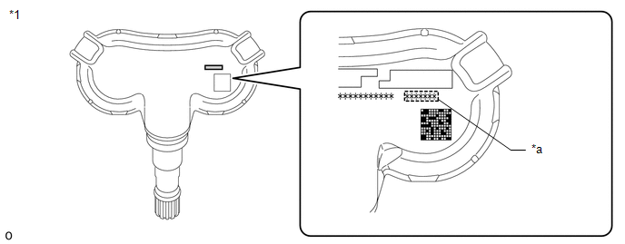
|
*1 | Tire Pressure Warning Valve and Transmitter |
*a | Transmitter ID (7-digit Number) |
NOTICE: For
vehicles equipped with the wheel speed type tire inflation pressure
display function, be sure to use tire pressure warning valve and
transmitters with identification marks. (h) Confirm that the ID number on the transmitter and recorded transmitter ID match.
|
Result | Proceed to | |
Match | A | |
Do not match | B |
| B |
| GO TO STEP 4 |
|
A | |
| |
| 3. |
REPLACE TIRE PRESSURE WARNING VALVE AND TRANSMITTER |
(a) Replace the tire pressure warning valve and transmitter. Click here
|
NEXT | |
| |
| 4. |
REGISTRATION OF TRANSMITTER ID | (a) Perform registration.
Click here
|
NEXT | |
| |
| 5. |
PERFORM INITIALIZATION | (a) Perform initialization.
Click here
|
NEXT | |
| |
| 6. |
CONFIRM TIRE INFLATION PRESSURE (DATA LIST) |
(a) Turn the ignition switch off. (b) Connect the Techstream to the DLC3.
(c) Turn the ignition switch to ON. (d) Turn the Techstream on.
(e) Enter the following menus: Chassis / Tire Pressure Monitor / Data List.
(f) Check the values by referring to the table below. Chassis > Tire Pressure Monitor > Data List |
Tester Display | Measurement Item |
Range | Normal Condition |
Diagnostic Note | |
ID 1 Tire Inflation Pressure |
ID1 tire inflation pressure |
min.: Absolute pressure (abs) / 0 kPa (0 kgf/cm2, 0 psi), Relative pressure (Gauge) / 0 kPa (0 kgf/cm2, 0 psi)
max.: Absolute pressure (abs) / 480 kPa (4.9 kgf/cm2, 70 psi), Relative pressure (Gauge) / 380 kPa (3.9 kgf/cm2, 55 psi) |
Actual tire inflation pressure |
If N/A is displayed, data has not been received.* | |
ID 2 Tire Inflation Pressure |
ID2 tire inflation pressure |
min.: Absolute pressure (abs) / 0 kPa (0 kgf/cm2, 0 psi), Relative pressure (Gauge) / 0 kPa (0 kgf/cm2, 0 psi)
max.: Absolute pressure (abs) / 480 kPa (4.9 kgf/cm2, 70 psi), Relative pressure (Gauge) / 380 kPa (3.9 kgf/cm2, 55 psi) |
Actual tire inflation pressure |
If N/A is displayed, data has not been received.* | |
ID 3 Tire Inflation Pressure |
ID3 tire inflation pressure |
min.: Absolute pressure (abs) / 0 kPa (0 kgf/cm2, 0 psi), Relative pressure (Gauge)/ 0 kPa (0 kgf/cm2, 0 psi)
max.: Absolute pressure (abs) / 480 kPa (4.9 kgf/cm2, 70 psi), Relative pressure (Gauge) / 380 kPa (3.9 kgf/cm2, 55 psi) |
Actual tire inflation pressure |
If N/A is displayed, data has not been received.* | |
ID 4 Tire Inflation Pressure |
ID4 tire inflation pressure |
min.: Absolute pressure (abs) / 0 kPa (0 kgf/cm2, 0 psi), Relative pressure (Gauge) / 0 kPa (0 kgf/cm2, 0 psi)
max.: Absolute pressure (abs) / 480 kPa (4.9 kgf/cm2, 70 psi), Relative pressure (Gauge) / 380 kPa (3.9 kgf/cm2, 55 psi) |
Actual tire inflation pressure |
If N/A is displayed, data has not been received.* |
HINT:
- *: It may take a few minutes until the values are displayed.
For this vehicle, data reception from the tire pressure
warning valve and transmitter may worsen while displaying the Data List
and it may takes longer than usual to receive data.
If
data reception worsens while displaying the Data List, rapidly decrease
the tire pressure by 20 to 30 kPa (this increases the valve
transmission frequency).
- The wheel position cannot be determined from ID1 through ID4 on the Data List.
- When an "ID Tire Inflation Pressure" value has not changed, reset the
tire pressure to the appropriate specified value and rotate the tire 90
to 270 degrees. Then rapidly release the tire pressure and recheck the
value.
|
Result | Proceed to | |
Tire pressure values are not displayed. |
A | | All tire pressure readings are equal to specified values. |
B |
| A |
| REPLACE TIRE PRESSURE WARNING ECU AND RECEIVER |
| B |
| END | |


