Toyota Tundra Service Manual: ECU Power Source Circuit

DESCRIPTION

The IG circuit is the power source for the tire pressure warning ECU and receiver.

WIRING DIAGRAM

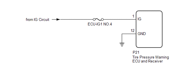
CAUTION / NOTICE / HINT

NOTICE:

  • When replacing the tire pressure warning ECU and receiver, read the transmitter IDs stored in the old ECU using the Techstream and write them down before removal.
  • It is necessary to perform initialization after registration of the transmitter IDs into the tire pressure warning ECU and receiver if the ECU has been replaced.

HINT:

Inspect the fuses for circuits related to this system before performing the following inspection procedure.

PROCEDURE

1.

CHECK HARNESS AND CONNECTOR (TIRE PRESSURE WARNING ECU AND RECEIVER POWER SOURCE)

(a) Disconnect the P21 tire pressure warning ECU and receiver connector.

*a

Front view of wire harness connector

(to Tire Pressure Warning ECU and Receiver)

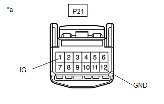
(b) Measure the voltage according to the value(s) in the table below.

Standard Voltage:

Tester Connection

Condition

Specified Condition

P21-1 (IG) - Body ground

Ignition switch ON

11 to 14 V

Ignition switch OFF

Below 1 V

(c) Measure the resistance according to the value(s) in the table below.

Standard Resistance:

Tester Connection

Condition

Specified Condition

P21-12 (GND) - Body ground

Always

Below 1 Ω

OK

REPLACE TIRE PRESSURE WARNING ECU AND RECEIVER

NG

REPAIR OR REPLACE HARNESS OR CONNECTOR

    Dtc Check / Clear

    Fail-safe Chart

    See More:

    Toyota Tundra Service Manual > Headlight Assembly(for Halogen Headlight): Installation
    INSTALLATION CAUTION / NOTICE / HINT HINT: Use the same procedure for the RH and LH sides. The procedure listed below is for the LH side. A bolt without a torque specification is shown in the standard bolt chart (See page ). PROCEDURE 1. INSTALL HEADLIGHT ASSEMBLY LH (a) Put protective tape around t ...

    Toyota Tundra Owners Manual

    Toyota Tundra Service Manual

    © 2024 Copyright www.ttundra.com
    0.014