REGISTRATION PROCEDURE 1. BEFORE REGISTRATION
NOTICE:
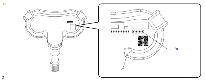
- The transmitter ID is written on the tire pressure warning valve and
transmitter. It is not possible to read the transmitter ID after
installing the tire onto the wheel. Therefore, make a note of the
transmitter ID before installing the tire.
- Tire pressure warning ECU and receiver ID registration after replacement must be performed using the Techstream.
(a) In case of tire pressure warning ECU and receiver replacement:
(1) Read the registered transmitter IDs that are stored in the old ECU using the Techstream and write them down.
(2)
If reading the stored transmitter IDs is impossible due to malfunctions
of components such as the tire pressure warning ECU and receiver,
remove the tires from the wheels and check the IDs located on the tire
pressure warning valve and transmitters. (b) In case of tire pressure warning valve and transmitter replacement:
(1) Take a note of the 7-digit number (transmitter ID) written on the tire pressure warning valve and transmitter.
|
*1 | Tire Pressure Warning Valve and Transmitter |
*a | Transmitter ID (7-digit Number) |
NOTICE: For
vehicles equipped with the wheel speed type tire inflation pressure
display function, be sure to use tire pressure warning valve and
transmitters with identification marks. 2. REGISTER TRANSMITTER ID (USING TECHSTREAM)
HINT:
- The previously registered IDs will be cleared from memory when the registration is completed.
- If the ID registration step is not completed within 300 seconds, ID registration will be canceled.
(a) Set the tire pressure to the specified value. Click here
 (b) Turn the ignition switch off.
(c) Connect the Techstream to the DLC3. (d) Turn the ignition switch to ON and the Techstream on.
(e) Enter the following menus: Chassis / Tire Pressure Monitor / Utility / ID Registration/Tire Number Registration.
(f) Perform the procedure displayed on the Techstream. 3. CONFIRMATION OF TRANSMITTER ID REGISTRATION (USING TECHSTREAM)
NOTICE:
- It may take a few minutes until the values are displayed. If the values
are not displayed after a few minutes, perform troubleshooting according
to the inspection procedure for DTCs C2121/21 to C2124/24.
Click here
- If the transmitter IDs have not been registered, DTC C2171/71 is stored
in the tire pressure warning ECU and receiver after 3 minutes or more.
- If normal pressure values are displayed, the transmitter IDs have been registered correctly.
- If the tire pressure values are not displayed after a few minutes, the
transmitter IDs may be incorrect or the system may have a malfunction.
- After all transmitter IDs are registered, DTC C2126/26 is stored in the
tire pressure warning ECU and receiver and the tire pressure warning
light blinks for 1 minute and then illuminates. When the tire pressure
warning ECU and receiver successfully receives signals from all the
transmitters whose IDs are stored in the ECU, DTC C2126/26 is cleared
and the tire pressure warning light goes off.
(a) Enter the following menus: Chassis / Tire Pressure Monitor / Data List. Chassis > Tire Pressure Monitor > Data List |
Tester Display | Measurement Item |
Range | Normal Condition |
Diagnostic Note | |
ID 1 Tire Inflation Pressure |
ID1 tire inflation pressure |
min.: Absolute pressure (abs) / 0 kPa (0 kgf/cm2, 0 psi), Relative pressure (Gauge) / 0 kPa (0 kgf/cm2, 0 psi)
max.: Absolute pressure (abs) / 480 kPa (4.9 kgf/cm2, 70 psi), Relative pressure (Gauge) / 380 kPa (3.9 kgf/cm2, 55 psi) |
Actual tire inflation pressure |
If N/A is displayed, data has not been received.* | |
ID 2 Tire Inflation Pressure |
ID2 tire inflation pressure |
min.: Absolute pressure (abs) / 0 kPa (0 kgf/cm2, 0 psi), Relative pressure (Gauge) / 0 kPa (0 kgf/cm2, 0 psi)
max.: Absolute pressure (abs) / 480 kPa (4.9 kgf/cm2, 70 psi), Relative pressure (Gauge) / 380 kPa (3.9 kgf/cm2, 55 psi) |
Actual tire inflation pressure |
If N/A is displayed, data has not been received.* | |
ID 3 Tire Inflation Pressure |
ID3 tire inflation pressure |
min.: Absolute pressure (abs) / 0 kPa (0 kgf/cm2, 0 psi), Relative pressure (Gauge) / 0 kPa (0 kgf/cm2, 0 psi)
max.: Absolute pressure (abs) / 480 kPa (4.9 kgf/cm2, 70 psi), Relative pressure (Gauge) / 380 kPa (3.9 kgf/cm2, 55 psi) |
Actual tire inflation pressure |
If N/A is displayed, data has not been received.* | |
ID 4 Tire Inflation Pressure |
ID4 tire inflation pressure |
min.: Absolute pressure (abs) / 0 kPa (0 kgf/cm2, 0 psi), Relative pressure (Gauge) / 0 kPa (0 kgf/cm2, 0 psi)
max.: Absolute pressure (abs) / 480 kPa (4.9 kgf/cm2, 70 psi), Relative pressure (Gauge) / 380 kPa (3.9 kgf/cm2, 55 psi) |
Actual tire inflation pressure |
If N/A is displayed, data has not been received.* |
HINT:
- *: It may take a few minutes until the values are displayed. If the
values are not displayed after a few minutes, perform troubleshooting
according to the inspection procedure for DTCs C2121/21 to C2124/24.
For this vehicle, data reception from the tire pressure
warning valve and transmitter may worsen while displaying the Data List
and it may takes longer than usual to receive data.
If
data reception worsens while displaying the Data List, rapidly decrease
the tire pressure by 20 to 30 kPa (this increases the valve
transmission frequency).
- The wheel position cannot be determined from ID1 through ID4 on the Data List.
(b) Reduce the tire inflation pressure
of each tire 40 kPa (0.4 kgf/cm2, 5.8 psi) or more, and check that the
"ID Tire Inflation Pressure" data is updated and that the actual tire
inflation pressures are displayed. (c) After
confirming that all of the tire inflation pressure values have been
updated, adjust the tire inflation pressure to the specified value,
press the tire pressure warning reset switch and perform initialization. 4. REGISTER TRANSMITTER ID (USING AUTOMATIC ID REGISTRATION FUNCTION)
NOTICE:
- If the automatic ID registration operation is canceled while
registration is being performed, DTC C2126/26 is stored in the tire
pressure warning ECU and receiver.
- If the automatic ID registration operation is canceled while
registration is being performed and restarted while DTC C2126/26 is
detected, DTC C2126/26 and C2128/28 is stored in the tire pressure
warning ECU and receiver.
- If DTC C2128/28 is output to the tire pressure warning ECU and receiver
during automatic registration, the tire pressure warning light
illuminates after blinking for 1 minute.
When all of IDs have been registered to the tire
pressure warning ECU and receiver, all the data from the tire pressure
warning valve and transmitter is sent to the tire pressure warning ECU
and receiver, DTC C2128/28 is cleared and the tire pressure warning
light turns off.
- If another tire pressure warning valve and transmitter belonging to the
same system is installed to a tire other than the one transmitter
registration is being performed on, automatic ID registration does not
complete.
HINT:
- When registration is complete, all previously registered IDs are cleared.
- Registration mode cannot be accessed even if registration work is
performed while DTCs C2176/76, C2179/79 and U0129/29 are output.
- Registration mode cannot be accessed even if registration work is
performed while the ECU Data List is being displayed using the
Techstream.
- If the ECU Data List is displayed using the Techstream while work is being performed, the registration mode will be canceled.
- If DTCs C2176/76, C2179/79 and U0129/29 are output while work is being performed, registration mode will be canceled.
- If the ignition switch is turned off before starting to drive while performing work, registration mode will be canceled.
(a) Adjust the tire pressure in all tires to the specified pressure.
(b) Turn the ignition switch off and stop the vehicle for 15 minutes or more.
HINT: After
stopping the vehicle for 15 minutes or more, the frequency of
electrical wave signals sent by the tire pressure warning valve and
transmitters increases for the first few minutes of driving (8 times the
normal frequency). (c) Press the tire pressure
warning reset switch turned on and off 3 times within 3 seconds (pressed
→ released → pressed → released → pressed → released). The tire pressure warning ECU and receiver switches to ID registration mode according to the automatic ID registration function.
HINT: Then
a message will be displayed on multi-information display. When
registration is being performed, the tire pressure warning light will
blink for approximately 1 minute then illuminate and "- -" will be
displayed for the inflation pressure of each tire on the
multi-information display. (d) Drive at approximately 37 km/h (23 mph) for approximately 10 to 30 minutes during 1 trip.
(e) During the procedure, make 2 or more right or left turns. HINT:
Do not drive the vehicle in reverse during registration. If
the vehicle is driven in reverse during registration, the information
may be reset before registration completes, and registration may take
longer than normal to complete. (f) When registration
is completed, the tire pressure warning light turns off, the normal tire
pressure is displayed on the multi-information display and "Tire
Pressure Recalibrating Please Wait until Complete" stops displaying.
HINT:
- Registration may take longer than normal in the following driving environments.
- Vehicle is often stopped
- Vehicle is stopped for long period of time
- Vehicle is driven in reverse
- Vehicle is driven parallel to another vehicle with the same type of tire
pressure warning valve and transmitter installed for a long duration of
time
- Vehicle was not stopped for 15 minutes or more before registration
- Vehicle was driven at 37 km/h (23 mph) or less for a long duration of time
- The ignition switch is turned from ON to off during ID registration
5. TIRE POSITION IDENTIFICATION (USING TECHSTREAM) (Tire Inflation Pressure Display Function)
(a) Set the tire pressure to the specified value. Click here
(b) Turn the ignition switch to ON and let the vehicle idle for 2 to 3 minutes.
HINT: For
this vehicle, it may take longer than usual to receive data from the
tire pressure warning valve and transmitter while the Data List is
displayed. Therefore, before displaying the Data List, wait 2 to 3
minutes to receive data from the tire pressure warning valve and
transmitter. (c) Turn the ignition switch off. (d) Connect the Techstream to the DLC3.
(e) Turn the ignition switch to ON and the Techstream on. (f) Enter the following menus: Chassis / Tire Pressure Monitor / Data List. Chassis > Tire Pressure Monitor > Data List |
Tester Display | Measurement Item |
Range | Normal Condition |
Diagnostic Note | |
ID 1 Tire Inflation Pressure |
ID1 tire inflation pressure |
min.: Absolute pressure (abs) / 0 kPa (0 kgf/cm2, 0 psi), Relative pressure (Gauge) / 0 kPa (0 kgf/cm2, 0 psi)
max.: Absolute pressure (abs) / 480 kPa (4.9 kgf/cm2, 70 psi), Relative pressure (Gauge) / 380 kPa (3.9 kgf/cm2, 55 psi) |
Actual tire inflation pressure |
If N/A is displayed, data has not been received.* | |
ID 2 Tire Inflation Pressure |
ID2 tire inflation pressure |
min.: Absolute pressure (abs) / 0 kPa (0 kgf/cm2, 0 psi), Relative pressure (Gauge) / 0 kPa (0 kgf/cm2, 0 psi)
max.: Absolute pressure (abs) / 480 kPa (4.9 kgf/cm2, 70 psi), Relative pressure (Gauge) / 380 kPa (3.9 kgf/cm2, 55 psi) |
Actual tire inflation pressure |
If N/A is displayed, data has not been received.* | |
ID 3 Tire Inflation Pressure |
ID3 tire inflation pressure |
min.: Absolute pressure (abs) / 0 kPa (0 kgf/cm2, 0 psi), Relative pressure (Gauge) / 0 kPa (0 kgf/cm2, 0 psi)
max.: Absolute pressure (abs) / 480 kPa (4.9 kgf/cm2, 70 psi), Relative pressure (Gauge) / 380 kPa (3.9 kgf/cm2, 55 psi) |
Actual tire inflation pressure |
If N/A is displayed, data has not been received.* | |
ID 4 Tire Inflation Pressure |
ID4 tire inflation pressure |
min.: Absolute pressure (abs) / 0 kPa (0 kgf/cm2, 0 psi), Relative pressure (Gauge) / 0 kPa (0 kgf/cm2, 0 psi)
max.: Absolute pressure (abs) / 480 kPa (4.9 kgf/cm2, 70 psi), Relative pressure (Gauge) / 380 kPa (3.9 kgf/cm2, 55 psi) |
Actual tire inflation pressure |
If N/A is displayed, data has not been received.* |
HINT:
- *: It may take a few minutes until the values are displayed.
- The wheel position cannot be determined from ID1 through ID4 on the Data List.
(g) Rapidly reduce the tire pressure for each wheel at least 40 kPa (0.4 kgf/cm2, 5.8 psi) within 30 seconds.
NOTICE:
- It may take a few minutes until the values are displayed.
- When an "ID Tire Inflation Pressure" value has not changed, reset the
tire pressure to the appropriate specified value and rotate the tire 90
to 270 degrees. Then rapidly release the tire pressure and recheck the
value.
(h) Read the "ID Tire Inflation
Pressure" value and identify the tire with reduced pressure, and record
the corresponding tire pressure warning valve and transmitter (ID1 to
ID4). (i) Repeat for each tire. (j) Set the tire pressure to the specified value.
Click here (k) Enter the following menus: Chassis / Tire Pressure Monitor / Utility / Tire Position Write.
(l) Perform the procedure displayed on the Techstream. 6. TIRE POSITION IDENTIFICATION (NOT USING TECHSTREAM) (Tire Inflation Pressure Display Function)
(a) Set the tire pressure to the specified value. Click here
(b)
Perform initialization to clear the existing tire position information,
then drive the vehicle at 40 km/h (25 mph) or more for 10 to 30 minutes
in 1 trip until each tire position is automatically identified.
HINT:
- Do not drive the vehicle in reverse gear while performing Tire Position
Identification. If the vehicle is driven in reverse gear while
performing Tire Position Identification, identification information will
be discarded and Tire Position Identification may take longer than
usual.
- When the vehicle is driven under the following conditions, Tire Position Identification may take longer than usual.
- The vehicle is stopped frequently.
- The vehicle is stopped for a long period of time.
- The vehicle is driven in reverse gear.
- The vehicle is driven on rough roads or uneven surfaces.
|


