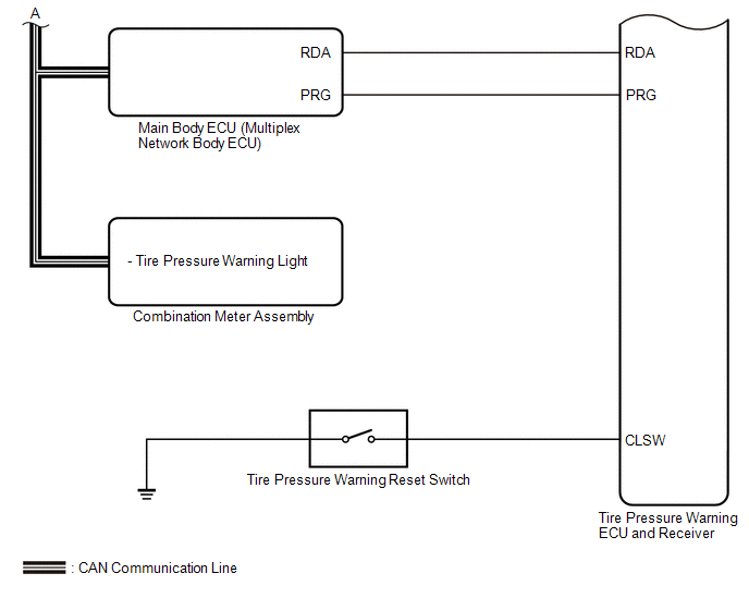
Toyota Tundra Service Manual: System Diagram

SYSTEM DIAGRAM

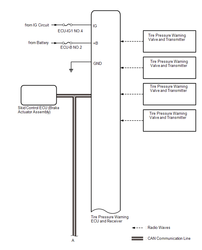
HINT:

Each tire pressure warning valve and transmitter sends its transmitter ID, temperature and tire pressure information to the tire pressure warning ECU and receiver.

Transmitting ECU (Transmitter)

Receiving ECU

Signal

Communication Method

Combination Meter Assembly

Main Body ECU (Multiplex Network Body ECU)

Vehicle speed signal

CAN communication line

Main Body ECU (Multiplex Network Body ECU)

Combination Meter Assembly

Tire pressure warning light signal

CAN communication line

Skid Control ECU (Brake Actuator Assembly)

Tire Pressure Warning ECU and Receiver

Speed sensor signal

CAN communication line

    Registration

    Terminals Of Ecu

    See More:

    Toyota Tundra Service Manual > Airbag System: Short in Knee Airbag (D Side) Squib Circuit (B1860-B1863)
    DESCRIPTION The driver side knee squib circuit consists of the airbag sensor assembly and lower No. 1 instrument panel airbag assembly. This circuit instructs the SRS to deploy when deployment conditions are met. These DTCs are stored when a malfunction is detected in the driver side knee squib circ ...

    Toyota Tundra Owners Manual

    Toyota Tundra Service Manual

    © 2024 Copyright www.ttundra.com
    0.0241