Toyota Tundra Service Manual: Terminals Of Ecu

TERMINALS OF ECU

CHECK TIRE PRESSURE WARNING ECU AND RECEIVER

(a) Disconnect the P21 tire pressure warning ECU and receiver connector and measure the voltage or resistance on the wire harness side.

*a

Front view of wire harness connector

(to Tire Pressure Warning ECU and Receiver)

Terminal No. (Symbol)

Wiring Color

Terminal Description

Condition

Specified Condition

P21-1 (IG) - P21-12 (GND)

R - W-B

IG power source

Ignition switch ON

10 to 16 V

P21-7 (+B) - P21-12 (GND)

LG - W-B

Power supply (from battery)

Always

10 to 16 V

P21-9 (CANH) - P21-10 (CANL)

SB - P

CAN communication line

Ignition switch OFF

54 to 69 Ω

P21-12 (GND) - Body ground

W-B - Body ground

Ground

Always

Below 1 Ω

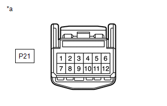
(b) Connect the P21 tire pressure warning ECU and receiver connector.

(c) Measure the voltage and resistance according to the value(s) in the table below. If the result is not as specified, the ECU may be malfunctioning.

HINT:

Measure the values on the wire harness side while the connector is connected.

*a

Component with harness connected

(Tire Pressure Warning ECU and Receiver)

-

-

Terminal No. (Symbol)

Wiring Color

Terminal Description

Condition

Specified Condition

P21-3 (CLSW) - P21-12 (GND)

W - W-B

Tire pressure warning reset switch

  • Ignition switch ON
  • Tire pressure warning reset switch on

Below 1.5 V

  • Ignition switch ON
  • Tire pressure warning reset switch off

8 to 15 V

P21-4 (RDA) - P21-12 (GND)

GR - W-B

Output signals

Ignition switch ON

Pulse generation (see waveform 1)

P21-5 (PRG) - P21-12 (GND)

L - W-B

Input signals

Ignition switch ON

Pulse generation (see waveform 1)

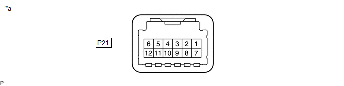
(d) Using an oscilloscope, check waveform 1.

*a

Example

*b

GND

Waveform 1:

Item

Contents

Terminal

P21-4 (RDA) - P21-12 (GND)

P21-5 (PRG) - P21-12 (GND)

Tool setting

5 V/DIV, 5 ms./DIV.

Vehicle condition

Ignition switch ON

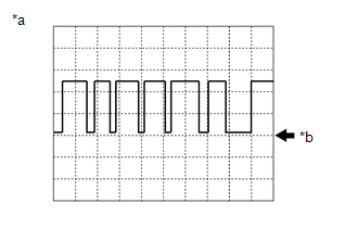
HINT:

The waveform shown in the illustration is an example. If the tester displays a waveform that alternates between high and low, where high is a voltage that is between the IG power source voltage and a voltage 2.2 V lower than the IG power source voltage, and where low is a voltage of between 0 and 1.2 V, the ECU can be judged normal.

    System Diagram

    Test Mode Procedure

    See More:

    Toyota Tundra Service Manual > Lighting System: LED Headlight LH Circuit Malfunction (B2430,B2431)
    DESCRIPTION The illumination of the low beam headlights is controlled by the main body ECU (multiplex network body ECU). When the headlights are turned on, the main body ECU (multiplex network body ECU) receives a signal from the headlight assembly and detects the illumination condition of the low b ...

    Toyota Tundra Owners Manual

    Toyota Tundra Service Manual

    © 2024 Copyright www.ttundra.com
    0.0097