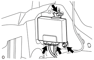
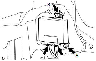
Components COMPONENTS ILLUSTRATION 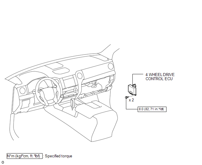 Installation INSTALLATION PROCEDURE 1. INSTALL 4 WHEEL DRIVE CONTROL ECU (a) Connect the 2 connectors.
2. INSTALL CLEARANCE WARNING ECU WITH BRACKET (See page
3. INSTALL LOWER INSTRUMENT PANEL FINISH PANEL SUB-ASSEMBLY RH
4. CONNECT CABLE TO NEGATIVE BATTERY TERMINAL NOTICE: When disconnecting the cable, some systems need to be initialized after the cable is reconnected (See page
Removal REMOVAL PROCEDURE 1. PRECAUTION NOTICE: After
turning the ignition switch off, waiting time may be required before
disconnecting the cable from the negative (-) battery terminal.
Therefore, make sure to read the disconnecting the cable from the
negative (-) battery terminal notice before proceeding with work (See
page 2. DISCONNECT CABLE FROM NEGATIVE BATTERY TERMINAL NOTICE: When disconnecting the cable, some systems need to be initialized after the cable is reconnected (See page
3. REMOVE LOWER INSTRUMENT PANEL FINISH PANEL SUB-ASSEMBLY RH
4. REMOVE CLEARANCE WARNING ECU WITH BRACKET (See page
5. REMOVE 4 WHEEL DRIVE CONTROL ECU
(b) Remove the 2 bolts and 4 wheel drive control ECU. NOTICE:
|
Toyota Tundra Service Manual > Ultrasonic Sensor(for Front Side): Removal
REMOVAL PROCEDURE 1. REMOVE RADIATOR GRILLE SUB-ASSEMBLY Click here 2. REMOVE FRONT BUMPER COVER Click here 3. REMOVE NO. 1 ULTRASONIC SENSOR RETAINER (for Steel Type Bumper) (a) Remove the No. 1 ultrasonic sensor retainer as shown in the illustration. HINT: The illustration shows the No. 1 ultrason ...

 )
)