DESCRIPTION This DTC is detected when a short to B+ is detected in the A.D.D. shift motor drive circuit.
WIRING DIAGRAM Refer to DTCs P17A0 and P17A1 (See page PROCEDURE
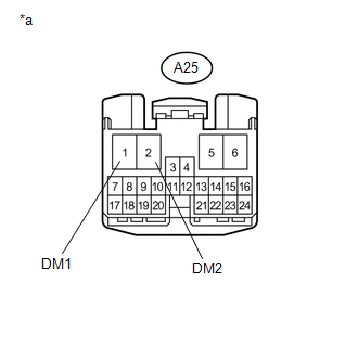 (a) Disconnect the 4 wheel drive control ECU connector. (b) Measure the voltage according to the value(s) in the table below. Standard Voltage:
(a) Disconnect the A25 4 wheel drive control ECU connector. (b) Disconnect the G1 A.D.D. actuator (differential vacuum actuator assembly) connector. (c) Measure the voltage according to the value(s) in the table below. Standard Voltage:
|
Toyota Tundra Service Manual > Sfi System: Evaporative Emission System Pressure Sensor - Manifold Absolute Pressure Correlation (P106A,P106B)
DESCRIPTION DTC No. DTC Detection Condition Trouble Area P106A The pressure detected by the canister pressure sensor (Vapor Pressure Pump*) and the pressure detected by the manifold absolute pressure sensor (MAP*) differ by 7 kPa (54 mmHg) or more (2 trip detection logic) Canister pressure sensor (c ...

 ).
).


