DESCRIPTION This DTC is detected when a short to B+ is detected in the transfer shift motor drive circuit.
WIRING DIAGRAM Refer to DTCs P17A8 and P17A9 (See page PROCEDURE
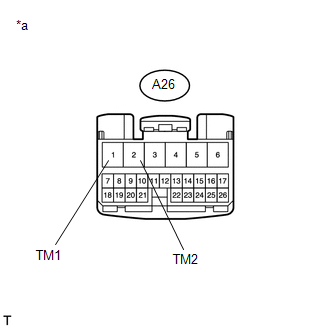 (a) Disconnect the 4 wheel drive control ECU connector. (b) Measure the voltage according to the value(s) in the table below. Standard Voltage:
(a) Disconnect the A26 4 wheel drive control ECU connector. (b) Disconnect the D67 transfer shift actuator assembly connector. (c) Measure the voltage according to the value(s) in the table below. Standard Voltage:
|
Toyota Tundra Service Manual > Engine Immobiliser System (w/o Smart Key System): Security Indicator Light Does not Blink
DESCRIPTION The transponder key ECU assembly blinks the security indicator light when the engine immobiliser is set. WIRING DIAGRAM CAUTION / NOTICE / HINT NOTICE: If the transponder key ECU assembly is replaced, refer to Registration. Click here PROCEDURE 1. PERFORM ACTIVE TEST USING TECHSTREAM (SE ...

 ).
).


