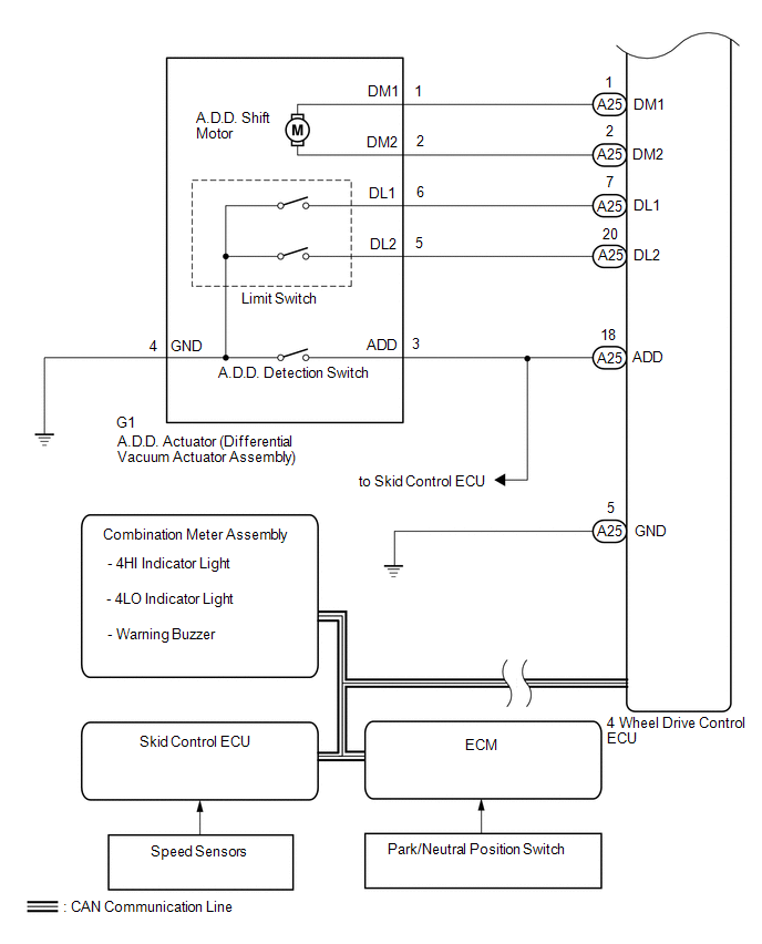
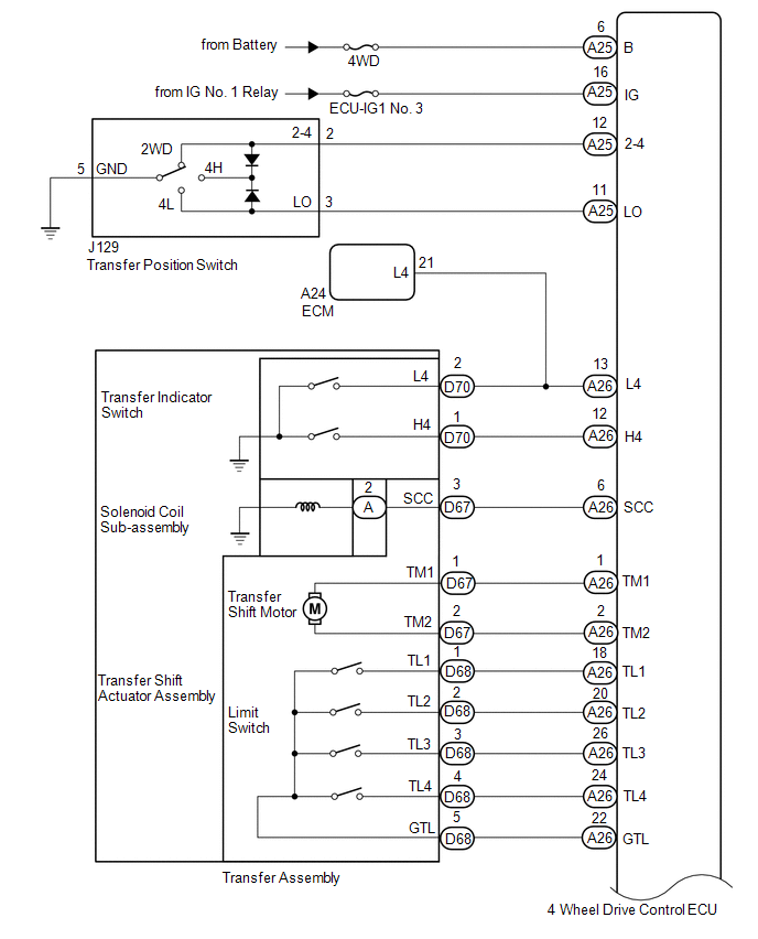
Toyota Tundra Service Manual: System Diagram

SYSTEM DIAGRAM

Transmitting ECU (Transmitter)

Receiving ECU

Signal

Communication Method

Skid control ECU

4 wheel drive control ECU

  • Wheel speed sensor error signal
  • Wheel speed signal
  • Vehicle wheel sensor power supply decline status signal
  • Vehicle speed signal

CAN communication system

ECM

4 wheel drive control ECU

  • Shift position P signal
  • Shift position N signal

CAN communication system

4 wheel drive control ECU

Combination meter assembly

  • 4WD indicator ON and flashing request signal
  • L4 indicator ON and flashing request signal
  • Buzzer sound demand signal

CAN communication system

4 wheel drive control ECU

Skid control ECU

  • Motor energizing signal
  • 4WD status signal
  • L4 status signal

CAN communication system

4 wheel drive control ECU

ECM

  • Cruise control cancel request signal
  • 4WD status signal

CAN communication system

    System Description

    Terminals Of Ecu

    See More:

    Toyota Tundra Service Manual > Brake Control / Dynamic Control Systems: Rear Speed Sensor
    ComponentsCOMPONENTS ILLUSTRATION InstallationINSTALLATION PROCEDURE 1. INSTALL SKID CONTROL SENSOR WIRE (a) Install the sensor clamp with the nut (labeled A). Torque: 15 N·m {153 kgf·cm, 11 ft·lbf} NOTICE: Make sure the clamp's rotation stopper touches the installation position. (b) Install the ...

    Toyota Tundra Owners Manual

    Toyota Tundra Service Manual

    © 2026 Copyright www.ttundra.com
    0.0296