|
Terminal No. (Symbol) | Wiring Color |
Terminal Description | Condition |
Specified Condition |
|
A25-1 (DM1) - A25-5 (GND) |
W - W-B | A. D. D. shift motor output |
Ignition switch ON Transfer position switch 4H → 2WD (during A.D.D. actuator Lock to Free operation) |
10 to 14 V |
|
A25-2 (DM2) - A25-5 (GND) |
Y - W-B | A. D. D. shift motor output |
Ignition switch ON Transfer position switch 2WD → 4H (during A.D.D. actuator Free to Lock operation) |
10 to 14 V |
|
A25-5 (GND) - Body ground | W-B - Body ground |
Ground | Always |
Below 1 Ω |
|
A25-6 (B) - A25-5 (GND) |
G - W-B | ECU power supply |
Always | 11 to 14 V |
|
A25-7 (DL1) - A25-5 (GND) |
LG - W-B | A.D.D. actuator limit switch input |
Ignition switch ON Transfer position 2WD (A.D.D. actuator Free) |
10.5 to 14 V |
| Ignition switch ON
Transfer position 4WD (A.D.D. actuator Lock) |
Below 1.5 V |
|
A25-11 (LO) - A25-5 (GND) |
P - W-B | Transfer position switch input |
Ignition switch ON Transfer position switch 2WD |
10.5 to 14 V |
| Ignition switch ON
Transfer position switch 4H |
Below 1.5 V |
| Ignition switch ON
Transfer position switch 4L |
Below 1 V |
|
A25-12 (2-4) - A25-5 (GND) |
B - W-B | Transfer position switch input |
Ignition switch ON Transfer position switch 2WD |
Below 1 V |
| Ignition switch ON
Transfer position switch 4H |
Below 1.5 V |
| Ignition switch ON
Transfer position switch 4L |
10.5 to 14 V |
|
A25-16 (IG) - A25-5 (GND) |
V - W-B | IG power |
Ignition switch ON | 11 to 14 V |
|
A25-18 (ADD) - A25-5 (GND) |
GR - W-B | A.D.D. detection switch input |
Ignition switch ON Transfer position 2WD |
10 to 14 V |
| Ignition switch ON
Transfer position 4WD |
Below 1.5 V |
|
A25-20 (DL2) - A25-5 (GND) |
R - W-B | A.D.D. actuator limit switch input |
Ignition switch ON Transfer position 2WD (A.D.D. actuator Free) |
Below 1.5 V |
| Ignition switch ON
Transfer position 4WD (A.D.D. actuator Lock) |
10.5 to 14 V |
|
A25-23 (CANH) - A25-22 (CANL) |
BE - W | CAN communication line |
Ignition switch off | 54 to 69 Ω |
|
A26-1 (TM1) - A25-5 (GND) |
R - W-B | Transfer shift motor output |
Ignition switch ON Shift lever in N Transfer position switch turned from 2WD to 4H (switching from 2WD to 4H)
Transfer position switch turned from 4H to 4L (switching from 4H to 4L) |
10 to 14 V |
|
A26-2 (TM2) - A25-5 (GND) |
W - W-B | Transfer shift motor output |
Ignition switch ON Shift lever in N Transfer position switch turned from 4L to 4H (switching from 4L to 4H)
Transfer position switch turned from 4H to 2WD (switching from 4H to 2WD) |
10 to 14 V |
|
A26-6 (SCC) - A25-5 (GND) |
L - W-B | Solenoid coil output |
Ignition switch ON Transfer position switch turned from 2WD to 4H (switching from 2WD to 4H)) |
10 to 14 V |
|
A26-12 (H4) - A25-5 (GND) |
BE - W-B | Transfer indicator switch input |
Ignition switch ON Transfer position not in 4L |
4 to 6 V |
| Ignition switch ON
Transfer position 4L |
Below 1.5 V |
|
A26-13 (L4) - A25-5 (GND) |
B - W-B | Transfer indicator switch input |
Ignition switch ON Transfer position not in 4L |
11 to 14 V |
| Ignition switch ON
Transfer position 4L |
Below 1.5 V |
|
A26-18 (TL1) - A25-5 (GND) |
V - W-B | Transfer shift actuator limit switch input |
Ignition switch ON Not switching driving mode |
4 to 6 V |
| Ignition switch ON
Switching driving mode |
4 to 6 V ←→ Below 1.5 V |
|
A26-20 (TL2) - A25-5 (GND) |
BR - W-B | Transfer shift actuator limit switch input |
Ignition switch ON Not switching driving mode |
4 to 6 V |
| Ignition switch ON
Switching driving mode |
4 to 6 V ←→ Below 1.5 V |
|
A26-22 (GTL) - A25-5 (GND) |
P - W-B | Transfer shift actuator limit switch GND input |
Ignition switch ON Not switching driving mode |
4 to 6 V |
| Ignition switch ON
Switching driving mode |
Below 1.5 V |
|
A26-24 (TL4) - A25-5 (GND) |
SB - W-B | Transfer shift actuator limit switch input |
Ignition switch ON Not switching driving mode |
4 to 6 V |
| Ignition switch ON
Switching driving mode |
4 to 6 V ←→ Below 1.5 V |
|
A26-26 (TL3) - A25-5 (GND) |
W - W-B | Transfer shift actuator limit switch input |
Ignition switch ON Not switching driving mode |
4 to 6 V |
| Ignition switch ON
Switching driving mode |
4 to 6 V ←→ Below 1.5 V |
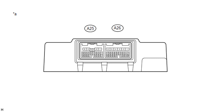 Text in Illustration

