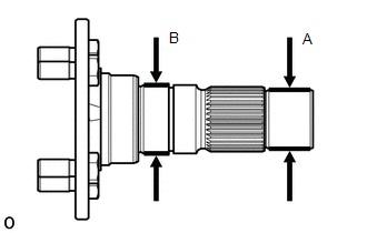
INSPECTION PROCEDURE 1. INSPECT OUTPUT SHAFT COMPANION FLANGE SUB-ASSEMBLY (FRONT)
| (a) Using a micrometer, measure the outer diameter of the output shaft companion flange sub-assembly (front) journal surface.
Minimum Diameter: |
Journal | Specified Condition | |
A | 34.962 mm (1.376 in.) | |
B | 39.955 mm (1.573 in.) |
If the outer diameter is less than the minimum, replace the output shaft companion flange sub-assembly (front). |
|
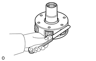
2. INSPECT TRANSFER LOW PLANETARY GEAR ASSEMBLY
| (a) Using a feeler gauge, measure the thrust clearance of the pinion gear.
Maximum clearance: 0.93 mm (0.037 in.) If the clearance is more than the maximum, replace the transfer low planetary gear assembly. |
|
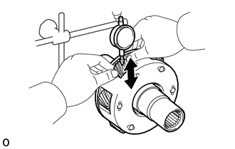
| (b) Using a dial indicator, measure the radial clearance of the pinion gear.
Maximum clearance: 0.021 mm (0.0008 in.) If the clearance is more than the maximum, replace the transfer low planetary gear assembly. |
|
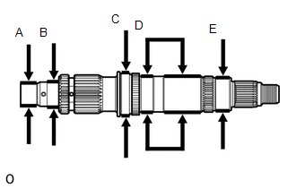
3. INSPECT REAR TRANSFER OUTPUT SHAFT
| (a) Using a micrometer, measure the diameter of the rear transfer output shaft journal.
Minimum Diameter: |
Journal | Specified Condition | |
A | 29.987 mm (1.181 in.) | |
B | 34.848 mm (1.372 in.) | |
C | 58.000 mm (2.284 in.) | |
D | 49.110 mm (1.934 in.) | |
E | 44.874 mm (1.767 in.) |
If the diameter is less than the minimum, replace the rear transfer output shaft. |
|
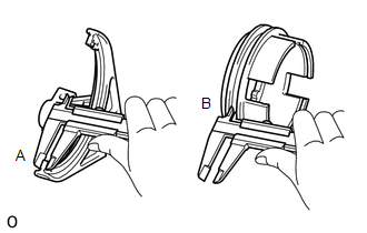
4. INSPECT SOLENOID LOCK PLATE AND NO. 2 TRANSFER GEAR SHIFT FORK CLEARANCE
| (a) Using a vernier caliper, measure the thickness of the No. 2 transfer gear shift fork claw.
Standard thickness (A): 6.90 to 7.06 mm (0.272 to 0.277 in.) |
|
(b) Using a vernier caliper, measure the width of the groove of the solenoid lock plate.
Standard width (B): 7.16 to 7.32 mm (0.282 to 0.288 in.) (c) Calculate the clearance between the solenoid lock plate and No. 2 transfer gear shift fork claw.
Maximum clearance (B) - (A): 0.42 mm (0.017 in.) If the clearance is more than the maximum, replace the solenoid lock plate or No. 2 transfer gear shift fork.
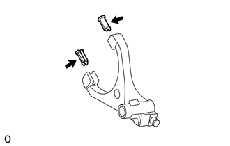
5. INSPECT NO. 1 TRANSFER GEAR SHIFT FORK AND NO. 2 TRANSFER GEAR SHIFT FORK
| (a) Check the gear shift fork pad for wear or damage. If necessary, replace the gear shift fork pad. |
|
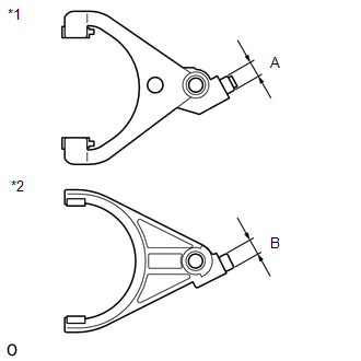
| (b) Using a micrometer, measure the outer diameter of the No. 1 transfer gear shift fork and No. 2 transfer gear shift fork.
Minimum Diameter: |
Diameter | Specified Condition | |
A | 12.586 mm (0.496 in.) | |
B | 12.586 mm (0.496 in.) | Text in Illustration |
*1 | No. 1 Transfer Gear Shift Fork | |
*2 | No. 2 Transfer Gear Shift Fork |
If the diameter is less than the minimum, replace the No. 1 transfer gear shift fork or No. 2 transfer gear shift fork. |
|
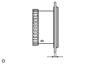
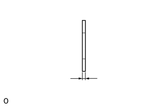
6. INSPECT TRANSFER HIGH AND LOW CLUTCH SLEEVE
| (a) Using a vernier caliper, measure the thickness of the transfer high and low clutch sleeve.
Minimum thickness: 3.00 mm (0.1182 in.) If the thickness is less than the minimum, replace the transfer high and low clutch sleeve. |
|
7. INSPECT TRANSFER OUTPUT SHAFT SPACER
| (a)
Using a vernier caliper, measure the thickness of the No. 1 transfer
output shaft spacer and No. 2 transfer output shaft spacer. Minimum Thickness: |
Transfer Output Shaft Spacer | Minimum Thickness | |
No. 1 Transfer Output Shaft Spacer |
2.80 mm (0.111 in.) | | No. 2 Transfer Output Shaft Spacer |
4.045 mm (0.160 in.) | If the thickness is less than the minimum, replace the transfer output shaft spacer. |
|
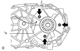
8. INSPECT SOLENOID COIL SUB-ASSEMBLY
| (a) Install the solenoid coil sub-assembly with the 3 nuts. Torque:
9.5 N·m {97 kgf·cm, 84 in·lbf} Text in Illustration |
*a | Rear Transfer Case Hole |
Make sure that the solenoid coil sub-assembly terminal extends out from the rear transfer case hole. |
|
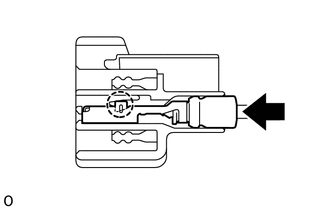
(b) Connect the solenoid coil sub-assembly terminal.
| (1) Attach the claw to connect the solenoid coil sub-assembly terminal. |
|
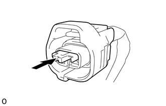
| (2) Install the retainer to the coupler. | |
(c) Measure the resistance according to the value(s) in the table below.
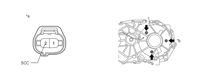 Standard Resistance: |
Tester Connection | Condition |
Specified Condition | |
2 (SCC) - Case GND | Always |
1.62 to 1.78 Ω | Text in Illustration |
*a | Component without harness connected
(Solenoid Coil Sub-assembly) | |
*b | Case GND |
HINT: For case ground, perform the measurement at one of the locations indicated by the arrows. |