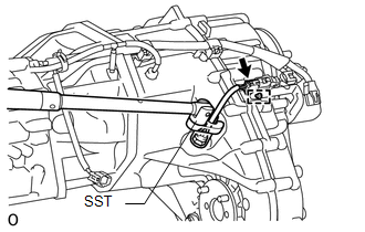
Components COMPONENTS ILLUSTRATION 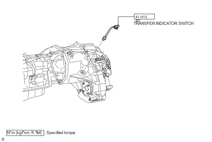 Inspection INSPECTION PROCEDURE 1. INSPECT TRANSFER INDICATOR SWITCH (a) Measure the resistance according to the value(s) in the table below. 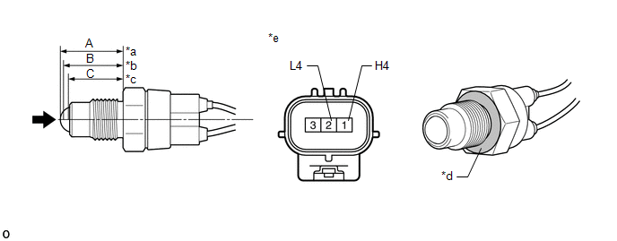 Dimension (A): 24.63 to 24.89 mm (0.970 to 0.979 in.) Dimension (B): 23.85 to 24.26 mm (0.939 to 0.955 in.) Dimension (C): 21.89 to 22.40 mm (0.862 to 0.881 in.) Text in Illustration
Standard Resistance:
If the resistance is not as specified, replace the transfer indicator switch. HINT: The ground is the nut of the transfer indicator switch (connecting surface with the transfer case). Installation INSTALLATION PROCEDURE 1. INSTALL TRANSFER INDICATOR SWITCH (a) Using SST, install the transfer indicator switch. SST: 09224-00010 Torque: 41 N·m {413 kgf·cm, 30 ft·lbf} NOTICE: Use the formula below to calculate special torque values for situations where SST is combined with a torque wrench (See page
(b) Connect the connector and attach the clamp. 2. INSTALL FRONT NO. 2 EXHAUST PIPE ASSEMBLY
3. INSTALL FRONT PROPELLER SHAFT ASSEMBLY (See page
Removal REMOVAL PROCEDURE 1. REMOVE FRONT PROPELLER SHAFT ASSEMBLY (See page
2. REMOVE FRONT NO. 2 EXHAUST PIPE ASSEMBLY
3. REMOVE TRANSFER INDICATOR SWITCH
(b) Using SST, remove the transfer indicator switch. SST: 09224-00010 |
Toyota Tundra Service Manual > Lane Departure Alert System: Steering Angle Sensor (C1A47)
DESCRIPTION The forward recognition camera receives steering angle information from the spiral with sensor cable sub-assembly. If the forward recognition camera detects a spiral with sensor cable sub-assembly, DTC C1A47 is stored. DTC No. Detection Item DTC Detection Condition Trouble Area C1A47 Ste ...


 )
)