CAUTION / NOTICE / HINT PRECAUTIONS WHEN TROUBLESHOOTING
NOTICE:
- Because the order of diagnosis is important to allow correct diagnosis,
make sure to begin troubleshooting using How to Proceed with
Troubleshooting when CAN communication system related DTCs are output.
- If the CAN communication system is malfunctioning, check the contact
pressure of the terminals in connectors, as insufficient terminal
contact pressure may be the cause.
Click here 
- Refer to Diagnosis System for CAN communication system DTCs.
- Refer to troubleshooting of each system if DTCs regarding the CAN communication system are not output.
- Before measuring the resistance of the CAN bus, turn the ignition switch
off and leave the vehicle for 1 minute or more without operating the
key or any switches, or opening or closing the doors. After that,
disconnect the cable from the negative (-) battery terminal and leave
the vehicle for 1 minute or more before measuring the resistance.
- After turning the ignition switch off, waiting time may be required
before disconnecting the cable from the negative (-) battery terminal.
Therefore, make sure to read the disconnecting the cable from the
negative (-) battery terminal notices before proceeding with work.
Click here
(a)
CAN communication DTCs are output for CAN main bus and CAN branch
malfunctions as well as for internal malfunctions or power source
malfunctions of ECUs or sensors for systems using CAN communication.
Therefore, when DTCs for internal malfunctions or power source
malfunctions of corresponding systems are output at the same time as CAN
communication DTCs, troubleshoot according to the internal malfunction
and power source malfunction DTCs. (b) An open in a
branch for ECUs or sensors that are connected to the CAN main bus can
be checked by performing a CAN bus check using the Techstream. (This
inspection is possible when all the main bus lines are normal.) (c)
If there was a communication error, the probable ECU or sensor for
which communication stopped can be determined using the combination of
communication DTCs (DTCs that start with U) that are output. (d)
If a sub bus has a communication error, the gateway function equipped
ECU (sub bus monitor ECU) detects it and stores DTCs related to the
error. HINT: On the Techstream, gateway function equipped ECUs display DTCs for ECUs connected to the sub bus.
(e)
When an open circuit is detected, before disconnecting related
connectors for inspection, push in on the connector body to check that
the connector is not loose or disconnected. (f) When a connector is disconnected, check that the terminals and connector body are not cracked, deformed or corroded. PROCEDURE
| 1. |
VEHICLE BROUGHT TO WORKSHOP |
HINT:
- If the ignition switch can be turned ON (the power source mode can be
changed to ON) when the vehicle is brought in for repair, check for DTCs
and check the illumination condition of the indicators in the
combination meter assembly and the basic operation of the vehicle (such
as steering operation) promptly.
- Do not turn the ignition switch off until the inspection of the vehicle
is finished, as some fail-safe functions are canceled when the ignition
switch is turned off.
- If the ignition switch cannot be turned ON (the power source mode cannot
be changed to ON) when the vehicle is brought in, measure the voltage
of the battery. If the voltage is below 11 V, recharge or replace the
battery before performing troubleshooting.
|
NEXT |
 | |
| 2. |
CUSTOMER PROBLEM ANALYSIS |
HINT:
- When troubleshooting, confirm that the problem symptoms have been
accurately identified. Preconceptions should be discarded in order to
make an accurate judgment. To clearly understand what the problem
symptoms are, it is extremely important to ask the customer about the
problem and the conditions at the time the malfunction occurred.
- Ask the customer if the vehicle is/was equipped with additional devices
such as a theft deterrent device or monitor. (If equipped, explain to
the customer that the additional devices will be removed before
performing troubleshooting as the malfunction cannot be checked
properly.)
- Examples of points to be confirmed are shown below.
(a) It is useful to confirm the
symptoms and the conditions in which the vehicle was operating at the
time when a malfunction occurred. This helps to narrow down the
malfunctioning part.
HINT:
- What was affected (system, part or meter warning indicators)
- What happened (details of the malfunction)
- When (occurrence date and time, frequency and if it recurs or not)
- Under what kind of situation did the problem occur (driving and operating condition at the occurrence and weather)
- Road type or condition (city, suburb, paved road, unpaved road, highway, etc.)
- Return conditions (what made the vehicle return to normal, for example, the ignition switch was turned off)
Points to be confirmed |
Symptom |
- Air conditioning
- Whether the air conditioning system operated
- Whether the blower fan operated
- The air conditioning functions cannot be operated at all
- Electric power steering
- Normal
- A little heavier than usual
- There was no assist
- Drive monitor display
- Whether the update of multi-information display items stopped
- Whether the numeric part of the drivable distance was displayed
- Not displayed at all
- Eco navigation (eco drive) display
- Whether the average fuel consumption graph is updated every minute
- Whether the updated section average fuel consumption graph is displayed
- Whether the distance-to-empty is displayed on the section average fuel consumption graph display
- Not displayed at all
- Interior lights
- Whether the interior light illumination changes when the door is opened or closed
- Whether the interior lights turned off when the ignition switch is turned ON
- Not illuminated at all
- Wireless door lock function and smart entry function
- Whether the lock/unlock function operated
- Whether the entry warning function operated
- Whether the illumination was turned on when the key was brought into a smart detection area
- 4WD/AWD operation
- Normal
- Slip detected when starting off
- Memory call
- Normal
- Memory write error
- Memory read error
- Whether the auto return or auto away control is performed
- Operation of other systems of concern
| | Meter warning lights |
- Illumination of warning lights and the order in which they illuminated
- Master
- Check engine (MIL)
- Brake
- ABS
- Slip
- EPS
- SRS
- Others
- Meter display
- Speedometer
- Tachometer
- Engine coolant temperature gauge
- Content displayed on the multi-information display
- Whether the odometer to TRIP meter has stopped
- Whether the value of the average fuel economy is displayed on the multi-information display
- Whether a warning message is displayed on the multi-information display
|
|
NEXT | |
| |
| 3. |
CHECK TECHSTREAM OPERATION | HINT:
Read the Techstream operator's manual before use. Click here
(a) Connect the Techstream to the DLC3.
(b) Turn the ignition switch to ON. (c) Turn the Techstream on.
(d) Check that the Techstream and ECUs can communicate with the ignition switch to ON.
HINT:
- If communication is not possible, the Techstream screen will indicate an error.
- If communication between the Techstream and ECUs is not possible, either the Techstream or vehicle has a malfunction.
- When communication between the Techstream and the vehicle is not
possible, but communication is possible when the Techstream is connected
to another vehicle, the vehicle is malfunctioning. Inspect the CANH and
CANL branch lines of the DLC3 and the ECU power source circuits (in
this case perform steps 30 to 31 first). In addition, check that the BAT
terminal of the DLC3 receives battery voltage (11 V or more).
- If communication between the Techstream and ECUs is still not possible
even when the Techstream is connected to another vehicle, the Techstream
has a malfunction. Perform the self tests described in the Techstream
operator's manual. (The Techstream may be malfunctioning or its battery
may be discharged.)
|
Result | Proceed to | |
Communication between the Techstream and the vehicle is possible. |
A | | Communication
between the Techstream and the vehicle is not possible but
communication is possible when connected to another vehicle. |
B | | Communication is not possible between the Techstream and the vehicle, nor between the Techstream and another vehicle. |
C |
| B |
 | GO TO STEP 30 |
| C |
| REFER TO TECHSTREAM OPERATOR'S MANUAL |
|
A | |
| |
| 4. |
CHECK DTC (CENTRAL GATEWAY ECU [NETWORK GATEWAY ECU]) |
(a) Connect the Techstream to the DLC3. (b) Turn the ignition switch to ON.
(c) Turn the Techstream on. (d) Enter the following menus: Body Electrical / Central Gateway / Trouble Codes.
OK: DTC B1003 is not output.
| OK |
| GO TO STEP 6 |
|
NG | |
| |
| 5. |
REPLACE CENTRAL GATEWAY ECU (NETWORK GATEWAY ECU) |
(a) Replace the central gateway ECU (network gateway ECU). Click here
HINT: DTC
B1003 is stored when a malfunction is detected in the non-volatile
storage of the central gateway ECU (network gateway ECU). As DTC B1003
is not related to a communication malfunction, continue with
troubleshooting to find the cause of the communication malfunction after
replacing the central gateway ECU (network gateway ECU).
|
NEXT | |
| |
(a) Using the Techstream, perform Health Check to read current and history DTCs and record them.
NOTICE:
- CAN communication DTCs are output when there is an open or short in any
of the communication lines. Any problems with the power source of a
corresponding ECU or sensor, or problems in the ECU or sensor itself
also cause these DTCs to be output.
- If a CAN communication line connector is disconnected with the ignition
switch to ON, the ECUs of the corresponding system and related systems
store a DTC.
HINT:
- If an open in a CAN main bus line, a short between the CAN bus lines
(CANH and CANL) or a short to ground or +B in a CAN bus occurs, DTCs of
almost all ECUs and sensors on the CAN bus may be output (or a message
indicating a communication error may be displayed on the Techstream
screen). In this case, check the resistance of the CAN bus (steps 9 to
23) first.
- If an open occurs in just one of the wires of a CAN branch line, DTCs
which are not related to malfunctioning parts may be output (DTCs may be
displayed randomly), or a message indicating a communication error may
be displayed.
(b) Read the freeze frame data using the Techstream and record it.
|
NEXT | |
| |
| 7. |
PERFORM COMMUNICATION MALFUNCTION CHECK (CONNECTION STATUS CHECK USING TECHSTREAM) |
(a) Select "Communication Malfunction Check" from the screen on the Techstream.
(b) Record all the DTCs stored for ECUs and sensors.
|
NEXT | |
| |
| 8. |
PERFORM CAN BUS CHECK (CONNECTION STATUS CHECK USING TECHSTREAM) |
(a) Based on the vehicle equipment and specifications, confirm the systems that use CAN communication.
Click here (b) Select "CAN Bus Check" from the screen on the Techstream.
(c) Observe the screen for approximately 2 minutes to check the ECUs and sensors displayed on the screen.
|
NEXT | |
| |
| 9. |
CHECK BUS 1 MAIN LINE (CANH - CANL) | NOTICE:
Before
measuring the resistance of the CAN bus, turn the ignition switch off
and leave the vehicle for 1 minute or more without operating the key or
any switches, or opening or closing the doors. After that, disconnect
the cable from the negative (-) battery terminal and leave the vehicle
for 1 minute or more before measuring the resistance. HINT: Operating
the ignition switch, any other switches or a door triggers related ECU
and sensor communication on the CAN. This communication will cause the
resistance value to change. |
(a) Measure the resistance according to the value(s) in the table below.
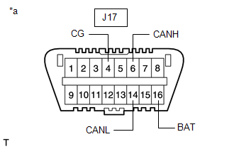
Standard Resistance: |
Tester Connection | Condition |
Specified Condition | |
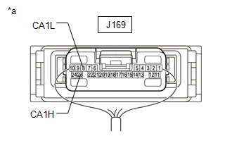
J169-23 (CA1H) - J169-8 (CA1L) |
Cable disconnected from negative (-) battery terminal |
54 to 69 Ω | |
 |
|
*a | Component with harness connected
(Central Gateway ECU [Network Gateway ECU]) | | |
|
Result | Proceed to | |
OK | A | |
NG (70 Ω or higher) | B | |
NG (Below 54 Ω) | C |
| B |
| GO TO OPEN IN BUS 1 MAIN BUS LINE |
| C |
| GO TO SHORT IN BUS 1 LINES |
|
A | |
| |
| 10. |
CHECK FOR SHORT TO GND IN BUS 1 (CANH, CANL - CG) |
| (a) Measure the resistance according to the value(s) in the table below.
Standard Resistance: |
Tester Connection | Condition |
Specified Condition | |
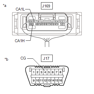
J169-23 (CA1H) - J17-4 (CG) |
Cable disconnected from negative (-) battery terminal |
200 Ω or higher | |
J169-8 (CA1L) - J17-4 (CG) | |
 |
|
*a | Component with harness connected
(Central Gateway ECU [Network Gateway ECU]) | |
*b | Front view of DLC3 | | |
| NG |
| GO TO SHORT TO GND IN BUS 1 LINE |
|
OK | |
| |
| 11. |
CHECK FOR SHORT TO +B IN BUS 1 (CANH, CANL - BAT) |
| (a) Measure the resistance according to the value(s) in the table below.
Standard Resistance: |
Tester Connection | Condition |
Specified Condition | |
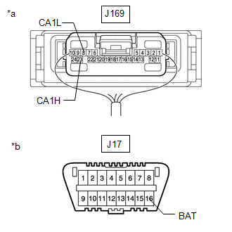
J169-23 (CA1H) - J17-16 (BAT) |
Cable disconnected from negative (-) battery terminal |
6 kΩ or higher | |
J169-8 (CA1L) - J17-16 (BAT) | |
 |
|
*a | Component with harness connected
(Central Gateway ECU [Network Gateway ECU]) | |
*b | Front view of DLC3 | | |
| NG |
| GO TO SHORT TO +B IN BUS 1 LINE |
|
OK | |
| |
| 12. |
CHECK BUS 2 MAIN LINE (CANH - CANL) | NOTICE:
Before
measuring the resistance of the CAN bus, turn the ignition switch off
and leave the vehicle for 1 minute or more without operating the key or
any switches, or opening or closing the doors. After that, disconnect
the cable from the negative (-) battery terminal and leave the vehicle
for 1 minute or more before measuring the resistance. HINT: Operating
the ignition switch, any other switches or a door triggers related ECU
and sensor communication on the CAN. This communication will cause the
resistance value to change. |
(a) Measure the resistance according to the value(s) in the table below.
Standard Resistance: |
Tester Connection | Condition |
Specified Condition | |
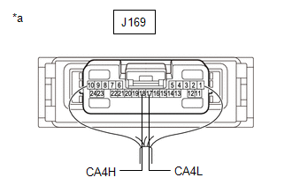
J169-18 (CA4H) - J169-17 (CA4L) |
Cable disconnected from negative (-) battery terminal |
54 to 69 Ω | |
 |
|
*a | Component with harness connected
(Central Gateway ECU [Network Gateway ECU]) | | |
|
Result | Proceed to | |
OK | A | |
NG (70 Ω or higher) | B | |
NG (Below 54 Ω) | C |
| B |
| GO TO OPEN IN BUS 2 MAIN BUS LINE |
| C |
| GO TO SHORT IN BUS 2 LINES |
|
A | |
| |
| 13. |
CHECK FOR SHORT TO GND IN BUS 2 (CANH, CANL - CG) |
| (a) Measure the resistance according to the value(s) in the table below.
Standard Resistance: |
Tester Connection | Condition |
Specified Condition | |
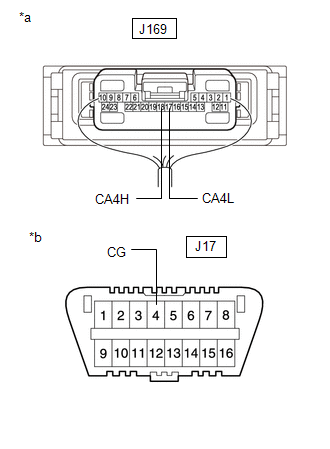
J169-18 (CA4H) - J17-4 (CG) |
Cable disconnected from negative (-) battery terminal |
200 Ω or higher | |
J169-17 (CA4L) - J17-4 (CG) | |
 |
|
*a | Component with harness connected
(Central Gateway ECU [Network Gateway ECU]) | |
*b | Front view of DLC3 | | |
| NG |
| GO TO SHORT TO GND IN BUS 2 LINE |
|
OK | |
| |
| 14. |
CHECK FOR SHORT TO +B IN BUS 2 (CANH, CANL - BAT) |
| (a) Measure the resistance according to the value(s) in the table below.
Standard Resistance: |
Tester Connection | Condition |
Specified Condition | |
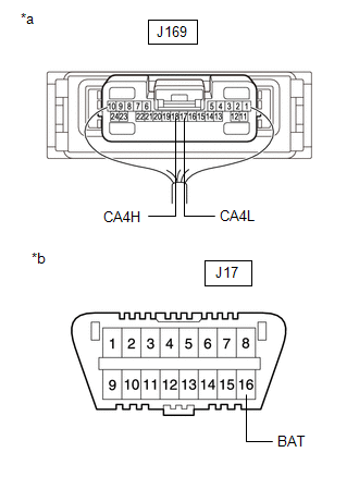
J169-18 (CA4H) - J17-16 (BAT) |
Cable disconnected from negative (-) battery terminal |
6 kΩ or higher | |
J169-17 (CA4L) - J17-16 (BAT) | |
 |
|
*a | Component with harness connected
(Central Gateway ECU [Network Gateway ECU]) | |
*b | Front view of DLC3 | | |
| NG |
| GO TO SHORT TO +B IN BUS 2 LINE |
|
OK | |
| |
| 15. |
CHECK BUS 3 MAIN LINE (CANH - CANL) | NOTICE:
Before
measuring the resistance of the CAN bus, turn the ignition switch off
and leave the vehicle for 1 minute or more without operating the key or
any switches, or opening or closing the doors. After that, disconnect
the cable from the negative (-) battery terminal and leave the vehicle
for 1 minute or more before measuring the resistance. HINT: Operating
the ignition switch, any other switches or a door triggers related ECU
and sensor communication on the CAN. This communication will cause the
resistance value to change. |
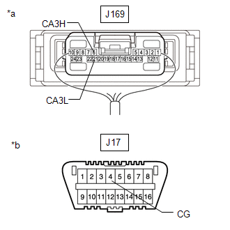
(a) Measure the resistance according to the value(s) in the table below.
Standard Resistance: |
Tester Connection | Condition |
Specified Condition | |
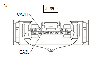
J169-6 (CA3H) - J169-21 (CA3L) |
Cable disconnected from negative (-) battery terminal |
54 to 69 Ω | |
 |
|
*a | Component with harness connected
(Central Gateway ECU [Network Gateway ECU]) | | |
|
Result | Proceed to | |
OK | A | |
NG (70 Ω or higher) | B | |
NG (Below 54 Ω) | C |
| B |
| GO TO OPEN IN BUS 3 MAIN BUS LINE |
| C |
| GO TO SHORT IN BUS 3 LINES |
|
A | |
| |
| 16. |
CHECK FOR SHORT TO GND IN BUS 3 (CANH, CANL - CG) |
| (a) Measure the resistance according to the value(s) in the table below.
Standard Resistance: |
Tester Connection | Condition |
Specified Condition | |
J169-6 (CA3H) - J17-4 (CG) |
Cable disconnected from negative (-) battery terminal |
200 Ω or higher | |
J169-21 (CA3L) - J17-4 (CG) | |
 |
|
*a | Component with harness connected
(Central Gateway ECU [Network Gateway ECU]) | |
*b | Front view of DLC3 | | |
| NG |
| GO TO SHORT TO GND IN BUS 3 LINE |
|
OK | |
| |
| 17. |
CHECK FOR SHORT TO +B IN BUS 3 (CANH, CANL - BAT) |
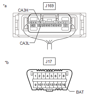
| (a) Measure the resistance according to the value(s) in the table below.
Standard Resistance: |
Tester Connection | Condition |
Specified Condition | |
J169-6 (CA3H) - J17-16 (BAT) |
Cable disconnected from negative (-) battery terminal |
6 kΩ or higher | |
J169-21 (CA3L) - J17-16 (BAT) | |
 |
|
*a | Component with harness connected
(Central Gateway ECU [Network Gateway ECU]) | |
*b | Front view of DLC3 | | |
| NG |
| GO TO SHORT TO +B IN BUS 3 LINE |
|
OK | |
| |
| 18. |
CHECK BUS 4 MAIN LINE (CANH - CANL) | NOTICE:
Before
measuring the resistance of the CAN bus, turn the ignition switch off
and leave the vehicle for 1 minute or more without operating the key or
any switches, or opening or closing the doors. After that, disconnect
the cable from the negative (-) battery terminal and leave the vehicle
for 1 minute or more before measuring the resistance. HINT: Operating
the ignition switch, any other switches or a door triggers related ECU
and sensor communication on the CAN. This communication will cause the
resistance value to change. |
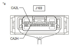
(a) Measure the resistance according to the value(s) in the table below.
Standard Resistance: |
Tester Connection | Condition |
Specified Condition | |
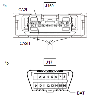
J169-22 (CA2H) - J169-7 (CA2L) |
Cable disconnected from negative (-) battery terminal |
54 to 69 Ω | |
 |
|
*a | Component with harness connected
(Central Gateway ECU [Network Gateway ECU]) | | |
|
Result | Proceed to | |
OK | A | |
NG (70 Ω or higher) | B | |
NG (Below 54 Ω) | C |
| B |
| GO TO OPEN IN BUS 4 MAIN BUS LINE |
| C |
| GO TO SHORT IN BUS 4 LINES |
|
A | |
| |
| 19. |
CHECK FOR SHORT TO GND IN BUS 4 (CANH, CANL - CG) |
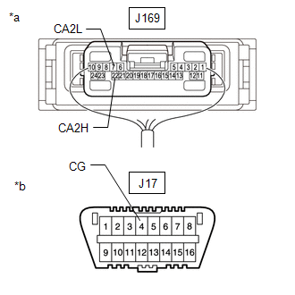
| (a) Measure the resistance according to the value(s) in the table below.
Standard Resistance: |
Tester Connection | Condition |
Specified Condition | |
J169-22 (CA2H) - J17-4 (CG) |
Cable disconnected from negative (-) battery terminal |
200 Ω or higher | |
J169-7 (CA2L) - J17-4 (CG) | |
 |
|
*a | Component with harness connected
(Central Gateway ECU [Network Gateway ECU]) | |
*b | Front view of DLC3 | | |
| NG |
| GO TO SHORT TO GND IN BUS 4 LINE |
|
OK | |
| |
| 20. |
CHECK FOR SHORT TO +B IN BUS 4 (CANH, CANL - BAT) |
| (a) Measure the resistance according to the value(s) in the table below.
Standard Resistance: |
Tester Connection | Condition |
Specified Condition | |
J169-22 (CA2H) - J17-16 (BAT) |
Cable disconnected from negative (-) battery terminal |
6 kΩ or higher | |
J169-7 (CA2L) - J17-16 (BAT) | |
 |
|
*a | Component with harness connected
(Central Gateway ECU [Network Gateway ECU]) | |
*b | Front view of DLC3 | | |
| NG |
| GO TO SHORT TO +B IN BUS 4 LINE |
|
OK | |
| |
| 21. |
CHECK BUS 5 MAIN LINE (CANH - CANL) | NOTICE:
Before
measuring the resistance of the CAN bus, turn the ignition switch off
and leave the vehicle for 1 minute or more without operating the key or
any switches, or opening or closing the doors. After that, disconnect
the cable from the negative (-) battery terminal and leave the vehicle
for 1 minute or more before measuring the resistance. HINT: Operating
the ignition switch, any other switches or a door triggers related ECU
and sensor communication on the CAN. This communication will cause the
resistance value to change. |
(a) Measure the resistance according to the value(s) in the table below.
Standard Resistance: |
Tester Connection | Condition |
Specified Condition | |
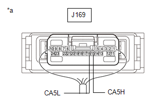
J169-15 (CA5H) - J169-16 (CA5L) |
Cable disconnected from negative (-) battery terminal |
54 to 69 Ω | |
 |
|
*a | Component with harness connected
(Central Gateway ECU [Network Gateway ECU]) | | |
|
Result | Proceed to | |
OK | A | |
NG (70 Ω or higher) | B | |
NG (Below 54 Ω) | C |
| B |
| GO TO OPEN IN BUS 5 MAIN BUS LINE |
| C |
| GO TO SHORT IN BUS 5 LINES |
|
A | |
| |
| 22. |
CHECK FOR SHORT TO GND IN BUS 5 (CANH, CANL - CG) |
| (a) Measure the resistance according to the value(s) in the table below.
Standard Resistance: |
Tester Connection | Condition |
Specified Condition | |
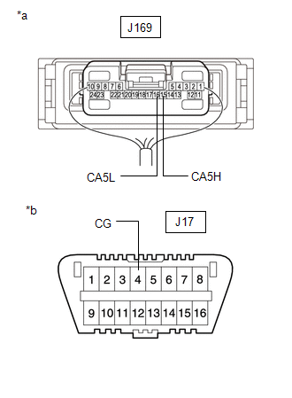
J169-15 (CA5H) - J17-4 (CG) |
Cable disconnected from negative (-) battery terminal |
200 Ω or higher | |
J169-16 (CA5L) - J17-4 (CG) | |
 |
|
*a | Component with harness connected
(Central Gateway ECU [Network Gateway ECU]) | |
*b | Front view of DLC3 | | |
| NG |
| GO TO SHORT TO GND IN BUS 5 LINE |
|
OK | |
| |
| 23. |
CHECK FOR SHORT TO +B IN BUS 5 (CANH, CANL - BAT) |
| (a) Measure the resistance according to the value(s) in the table below.
Standard Resistance: |
Tester Connection | Condition |
Specified Condition | |
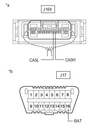
J169-15 (CA5H) - J17-16 (BAT) |
Cable disconnected from negative (-) battery terminal |
6 kΩ or higher | |
J169-16 (CA5L) - J17-16 (BAT) | |
 |
|
*a | Component with harness connected
(Central Gateway ECU [Network Gateway ECU]) | |
*b | Front view of DLC3 | | |
| NG |
| GO TO SHORT TO +B IN BUS 5 LINE |
|
OK | |
| |
| 24. |
CHECK RESULT OF CAN BUS CHECK (CONNECTION STATUS CHECK USING TECHSTREAM) |
(a)
Inspect or repair the probable malfunctioning part based on the check
result of step 8 (the step in which CAN bus check was performed). Result of CAN Bus Check (Connection Status Check Using Techstream):
|
Result | Proceed to | |
All ECUs and sensors connected to the CAN communication system are displayed as normal on the screen.
(CAN bus circuit is currently normal.) |
A |
- All ECUs except the main body ECU (multiplex network body ECU) connected
to sub bus 1 are displayed as communication stop on the screen.
- The main body ECU (multiplex network body ECU) (Main Body) outputs DTC U1002.
(Open or short in sub bus 1 main lines.) |
B | | The
main body ECU (multiplex network body ECU) is displayed as
communication stop on the screen, and all ECUs except the main body ECU
(multiplex network body ECU) connected to sub bus 1 are not displayed on
the screen. (Open in main body ECU (multiplex network body ECU) branch lines or main body ECU (multiplex network body ECU) malfunction.) |
C | | One of the ECUs or sensors connected to the bus 1, bus 3, bus 4 or bus 5 is displayed as communication stop on the screen.
(Open in ECU or sensor branch lines, or communication is interrupted.) |
D | | One of the ECUs or sensors connected to sub bus 1 is displayed as communication stop on the screen.*
(Open in ECU or sensor branch lines, or communication is interrupted.) |
E | | In
addition to ECUs and sensors which are connected to the bus 1 but are
displayed as communication stop on the screen, there are ECUs or sensors
for which the detection status changes (changes between detected and
not detected) during the inspection. (Open in one side of ECU or sensor branch lines.) |
F | | In
addition to ECUs and sensors which are connected to the bus 3 but are
displayed as communication stop on the screen, there are ECUs or sensors
for which the detection status changes (changes between detected and
not detected) during the inspection. (Open in one side of ECU or sensor branch lines.) |
G | | In
addition to ECUs and sensors which are connected to the bus 4 but are
displayed as communication stop on the screen, there are ECUs or sensors
for which the detection status changes (changes between detected and
not detected) during the inspection. (Open in one side of ECU or sensor branch lines.) |
H | | In
addition to ECUs and sensors which are connected to the bus 5 but are
displayed as communication stop on the screen, there are ECUs or sensors
for which the detection status changes (changes between detected and
not detected) during the inspection. (Open in one side of ECU or sensor branch lines.) |
I |
NOTICE:
- *: In this case, as the main body ECU (multiplex network body ECU)
outputs communication DTCs (DTCs that start with U), the problem area
can be determined from those DTCs.
- Non-installed ECUs or sensors will not be displayed. Do not mistake them for being in communication stop mode.
- It may be possible to select buses that do not have ECUs or sensors from
the bus selection pull-down menu on the Techstream. This is not a
malfunction. (This occurs when optional devices are not on a sub bus
that is monitored by a gateway function equipped ECU.)
HINT:
- Regarding CAN Bus Check, refer to How to Interpret CAN Bus Check Screen.
Click here
- If the detection status of any ECU changes during the inspection, one of
the branch lines of a connected ECU or sensor may be open. (Signals
from the ECU or sensor that has an open in one of its branch lines
create electrical noise, affecting response to the Techstream and
whether or not the ECUs and sensors are displayed.)
- Regarding the ECUs connected to sub bus 1, the main body ECU (multiplex
network body ECU) displays communicating ECUs on the Techstream. If the
communication between the main body ECU (multiplex network body ECU) and
an ECU stops for 10 seconds or more, the ECU will no longer be
displayed on the Techstream.
- Regarding the communication stop mode for ECUs connected to sub bus 1,
refer to the inspection procedure for the DTCs that indicate a
communication stop.
| B |
| GO TO U1002 |
| C |
| GO TO MAIN BODY ECU COMMUNICATION STOP MODE |
| D |
| GO TO COMMUNICATION STOP MODE TABLE |
| E |
| GO TO DIAGNOSTIC TROUBLE CODE CHART |
| F |
| GO TO OPEN IN ONE SIDE OF BUS 1 BRANCH LINE |
| G |
| GO TO OPEN IN ONE SIDE OF BUS 3 BRANCH LINE |
| H |
| GO TO OPEN IN ONE SIDE OF BUS 4 BRANCH LINE |
| I |
| GO TO OPEN IN ONE SIDE OF BUS 5 BRANCH LINE |
|
A | |
| |
| 25. |
CHECK RESULT OF COMMUNICATION MALFUNCTION CHECK (SELECT THE MALFUNCTIONING BUS) |
(a)
Inspect or repair the probable malfunctioning part based on the check
result of step 7 (the step in which checking for communication
malfunction DTCs was performed). Result of Communication Malfunction Check (Select Malfunctioning Bus):
|
Result | Proceed to | |
The
sub bus monitor ECU has not output communication DTCs but ECUs
connected to the bus 1, bus 2, bus 3, bus 4 or bus 5 have stored
communication DTCs. (A malfunction occurred in the bus 1, bus 2, bus 3, bus 4 or bus 5.) |
A | | The main body ECU (multiplex network body ECU) (Main Body) outputs DTC U1002.
(A malfunction occurred in sub bus 1.) |
B | | The main body ECU (multiplex network body ECU) (Main Body) outputs DTCs other than DTC U1002.
(A malfunction occurred in an ECU branch line connected to sub bus 1.) |
C |
HINT:
- The term ''sub bus monitor ECU'' refers to a gateway function equipped ECU that is able to monitor a bus and store DTCs.
- When checking for communication DTCs, refer to How to Interpret Communication DTCs (DTCs that start with U).
Click here
- Because a gateway function equipped ECU (sub bus monitor ECU) monitors
signals from all ECUs that are connected to its sub bus, a gateway
function equipped ECU can detect ECUs with a communication stop more
accurately. In this case, perform troubleshooting by referring to the
DTC combination table for the sub bus.
Click here
- If communication DTCs are stored, and all ECUs and sensors connected to
the CAN communication system are displayed on the CAN Bus Check screen
of the Techstream, a past malfunction that is currently not occurring is
suspected.
- When a CAN branch of the bus 1 and bus 5 is malfunctioning, because the
ECUs and sensors related to it detect the malfunction, the problem area
can be determined using the combination of DTCs that are output.
- When sub bus 1 is malfunctioning, the main body ECU (multiplex network
body ECU) detects a communication stop for connected ECUs and a network
communication error, and stores DTCs.
- On the Techstream, the Main Body item displays the DTCs for ECUs connected to sub bus 1.
- When both the sub bus monitor ECU and the ECUs connected to the bus 1,
bus 2, bus 3, bus 4 or bus 5 store communication DTCs, check and repair
the corresponding sub bus first.
| B |
| GO TO U1002 |
| C |
| GO TO DIAGNOSTIC TROUBLE CODE CHART |
|
A | |
| |
| 26. |
DTC COMBINATION TABLE | (a) Confirm the problem according to the combination of output DTCs regarding the CAN communication system.
Click here
|
Result | Proceed to | |
Combination of DTCs is not in DTC Combination Table |
A | | Combination of DTCs is in DTC Combination Table |
B | HINT: CAN
communication system history DTCs may indicate the problem if CAN
communication system DTCs are output and all ECUs and sensors connected
to the CAN communication system are displayed on the CAN Bus Check
screen of the Techstream.
| B | |
GO TO COMMUNICATION STOP MODE TABLE |
|
A | |
| |
| 27. |
IDENTIFICATION OF PROBLEM (PAST MALFUNCTION IN MAIN BUS OF EACH BUS) |
(a) Connect the cable to the negative (-) battery terminal. (b) Clear the DTCs using the Techstream.
(c) Perform the tests in Symptom Simulation to check the wire harnesses and connectors including those for main bus lines.
Click here (d) Based on the results of the check, inspect the parts that output DTCs to determine the malfunctioning part.
HINT: If DTCs are output, do not turn the ignition switch off.
|
NEXT | |
| |
| 28. |
REPAIR OR REPLACEMENT |
|
NEXT | |
| |
| NEXT |
| END |
| 30. |
CHECK V BUS BRANCH LINE (DLC3 - CENTRAL GATEWAY ECU [NETWORK GATEWAY ECU]) |
NOTICE: Before
measuring the resistance of the CAN bus, turn the ignition switch off
and leave the vehicle for 1 minute or more without operating the key or
any switches, or opening or closing the doors. After that, disconnect
the cable from the negative (-) battery terminal and leave the vehicle
for 1 minute or more before measuring the resistance. HINT: Operating
the ignition switch, any other switches or a door triggers related ECU
and sensor communication on the CAN. This communication will cause the
resistance value to change. (a) Disconnect the cable from the negative (-) battery terminal.
| (b) Measure the resistance according to the value(s) in the table below.
Standard Resistance: |
Tester Connection | Condition |
Specified Condition | |
J17-6 (CANH) - J17-14 (CANL) |
Cable disconnected from negative (-) battery terminal |
54 to 69 Ω | |
J17-6 (CANH) - J173-4 (CG) |
Cable disconnected from negative (-) battery terminal |
200 Ω or higher | |
J17-14 (CANL) - J17-4 (CG) |
Cable disconnected from negative (-) battery terminal |
200 Ω or higher | |
J17-6 (CANH) - J17-16 (BAT) |
Cable disconnected from negative (-) battery terminal |
6 kΩ or higher | |
J17-14 (CANL) - J17-16 (BAT) |
Cable disconnected from negative (-) battery terminal |
6 kΩ or higher | | |
| NG |
| REPAIR OR REPLACE CAN MAIN BUS LINE OR CONNECTOR (CENTRAL GATEWAY ECU [NETWORK GATEWAY ECU] - DLC3) |
|
OK | |
| |
| 31. |
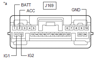
CHECK HARNESS AND CONNECTOR (POWER SOURCE CIRCUIT) |
(a) Disconnect the central gateway ECU (network gateway ECU) connector.
| (b) Measure the resistance according to the value(s) in the table below.
Standard Resistance: |
Tester Connection | Condition |
Specified Condition | |
J169-10 (GND) - Body ground |
Cable disconnected from negative (-) battery terminal |
Below 1 Ω | |
 |
|
*a | Front view of wire harness connector
(to Central Gateway ECU [Network Gateway ECU]) | | |
(c) Reconnect the cable to the negative (-) battery terminal. NOTICE:
When disconnecting the cable, some systems need to be initialized after the cable is reconnected.
Click here (d) Measure the voltage according to the value(s) in the table below.
Standard Voltage: |
Tester Connection | Condition |
Specified Condition | |
J169-1 (BATT) - Body ground |
Always | 11 to 14 V | |
J169-2 (ACC) - Body ground |
Ignition switch ACC | 11 to 14 V | |
Ignition switch off | Below 1 V | |
J169-11 (IG1) - Body ground |
Ignition switch ON | 11 to 14 V | |
Ignition switch off | Below 1 V | |
J169-12 (IG2) - Body ground |
Ignition switch ON | 11 to 14 V | |
Ignition switch off | Below 1 V |
| OK |
| REPLACE CENTRAL GATEWAY ECU (NETWORK GATEWAY ECU) |
| NG |
| REPAIR OR REPLACE HARNESS OR CONNECTOR (POWER SOURCE CIRCUIT) | |