Toyota Tundra Service Manual: Components

COMPONENTS

ILLUSTRATION
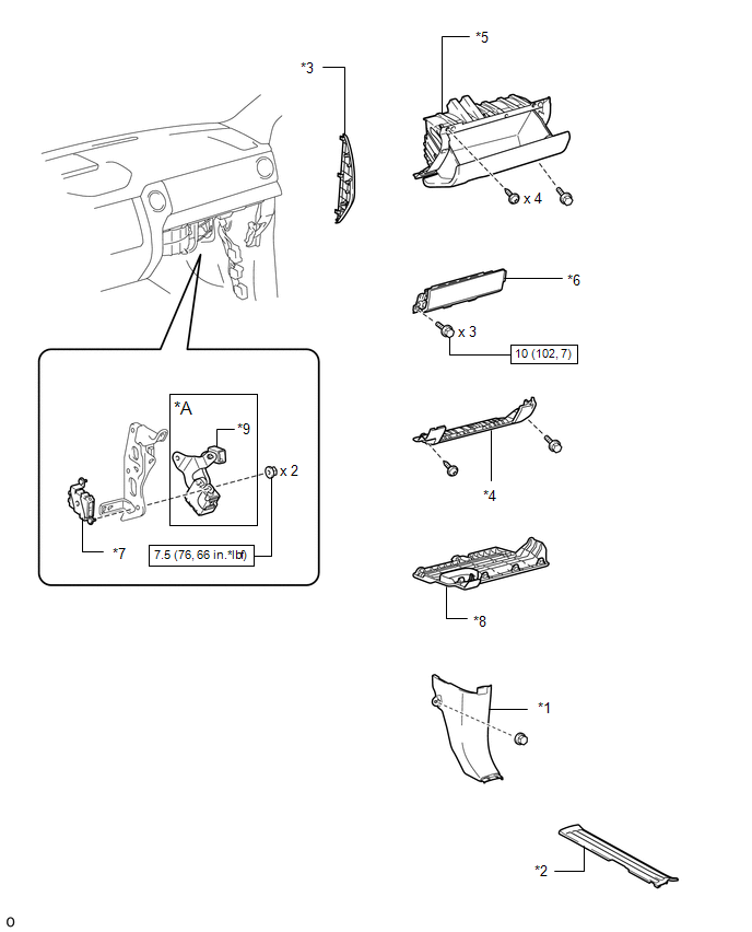
*A

for Column Shift Type

-

-

*1

COWL SIDE TRIM BOARD RH

*2

FRONT DOOR SCUFF PLATE RH

*3

INSTRUMENT SIDE PANEL RH

*4

LOWER INSTRUMENT PANEL

*5

LOWER INSTRUMENT PANEL FINISH PANEL SUB-ASSEMBLY RH

*6

LOWER NO. 2 INSTRUMENT PANEL AIRBAG ASSEMBLY

*7

NETWORK GATEWAY ECU

*8

NO. 2 INSTRUMENT PANEL UNDER COVER SUB-ASSEMBLY

*9

SHIFT LOCK CONTROL ECU

-

-

N*m (kgf*cm, ft.*lbf): Specified torque

-

-

    Network Gateway Ecu

    Installation

    See More:

    Toyota Tundra Service Manual > Sfi System: Crankshaft Position - Camshaft Position Correlation (Bank 1 Sensor A) (P0016-P0019)
    DESCRIPTION In the VVT (Variable Valve Timing) system, the appropriate intake and exhaust valve open and close timing is controlled by the ECM. The ECM performs intake and exhaust valve control by performing the following: 1) controlling the camshaft and camshaft timing oil control valve, and operat ...

    Toyota Tundra Owners Manual

    Toyota Tundra Service Manual

    © 2026 Copyright www.ttundra.com
    0.0302