DESCRIPTION This DTC is stored when LIN communication between the power window regulator master switch assembly and main body ECU (multiplex network body ECU) stops for 10 seconds or more.
WIRING DIAGRAM 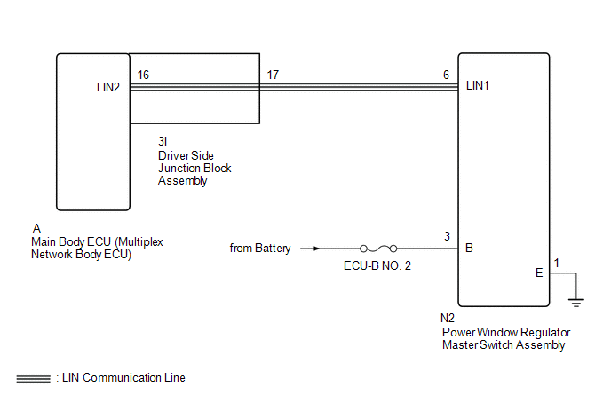 CAUTION / NOTICE / HINT NOTICE:
HINT: DTC B2325 is output when the communication between all of the following components and main body ECU (multiplex network body ECU) stops. Click here
PROCEDURE
(a) Clear the DTCs. Click here
(a) Check for DTCs. Click here
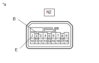
(a) Remove the main body ECU (multiplex network body ECU) from the driver side junction block assembly. Click here (b) Disconnect the N2 power window regulator master switch assembly connector. (c) Measure the resistance according to the value(s) in the table below. Standard Resistance:
(b) Measure the resistance according to the value(s) in the table below. Standard Resistance:
(c) Measure the voltage according to the value(s) in the table below. Standard Voltage:
(a) Temporarily replace the power window regulator master switch assembly with a new or normally functioning one. Click here (b) Clear the DTCs. Click here
(a) Check for DTCs. Click here
(a) Remove the main body ECU (multiplex network body ECU) from the driver side junction block assembly. Click here (b) Disconnect the N2 power window regulator master switch assembly connector. (c) Measure the resistance according to the value(s) in the table below. Standard Resistance:
|
Toyota Tundra Service Manual > Lane Departure Alert System: Lost Communication with Cruise Control Front Distance Range Sensor (U0235)
DESCRIPTION The forward recognition camera communicates with the millimeter wave radar sensor assembly via CAN communication. If there is a communication error with the millimeter wave radar sensor assembly, the forward recognition camera stores DTC U0235. DTC No. Detection Item DTC Detection Condit ...