Toyota Tundra Service Manual: Front Passenger Side Door ECU Communication Stop (B2322)

Toyota Tundra Service Manual / Power Source, Network / Multiplex Communication / Lin Communication System / Front Passenger Side Door ECU Communication Stop (B2322)

DESCRIPTION

This DTC is stored when LIN communication between the front power window regulator motor assembly RH and main body ECU (multiplex network body ECU) stops for 10 seconds or more.

DTC No.

DTC Detection Condition

Trouble Area

B2322

No communication between the front power window regulator motor assembly RH and main body ECU (multiplex network body ECU) for 10 seconds or more.

  • Front power window regulator motor assembly RH
  • Main body ECU (multiplex network body ECU)
  • Driver side junction block assembly
  • Harness or connector

WIRING DIAGRAM

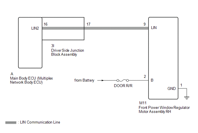
CAUTION / NOTICE / HINT

NOTICE:

  • When using the Techstream with the engine switch off to troubleshoot:

    Connect the Techstream to the vehicle and turn a courtesy light switch on and off at 1.5 second intervals until communication between the Techstream and vehicle begins.

  • Inspect the fuses for circuits related to this system before performing the following procedure.
  • When a power window regulator motor assembly is replaced or removed and reinstalled, it must be initialized.

    Click here

HINT:

DTC B2325 is output when the communication between all of the following components and main body ECU (multiplex network body ECU) stops.

Click here

PROCEDURE

1.

CLEAR DTC

(a) Clear the DTCs.

Click here

NEXT

2.

CHECK FOR DTC

(a) Check for DTCs.

Click here

DTC B2322 is not output

USE SIMULATION METHOD TO CHECK

DTC B2322 is output

3.

CHECK HARNESS AND CONNECTOR (MAIN BODY ECU [MULTIPLEX NETWORK BODY ECU] - FRONT POWER WINDOW REGULATOR MOTOR ASSEMBLY RH)

(a) Remove the main body ECU (multiplex network body ECU) from the driver side junction block assembly.

Click here

(b) Disconnect the M11 front power window regulator motor assembly RH connector.

(c) Measure the resistance according to the value(s) in the table below.

Standard Resistance:

Tester Connection

Condition

Specified Condition

A-16 (LIN2) - M11-9 (LIN)

Always

Below 1 Ω

A-16 (LIN2) - Body ground

Always

10 kΩ or higher

NG

GO TO STEP 7

OK

4.

CHECK HARNESS AND CONNECTOR (FRONT POWER WINDOW REGULATOR MOTOR ASSEMBLY RH - BATTERY AND BODY GROUND)

*a

Front view of wire harness connector

(to Front Power Window Regulator Motor Assembly RH)

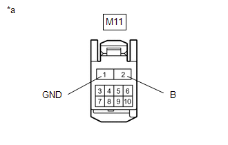
(a) Disconnect the front power window regulator motor assembly RH connector.

(b) Measure the resistance according to the value(s) in the table below.

Standard Resistance:

Tester Connection

Condition

Specified Condition

M11-1 (GND) - Body ground

Always

Below 1 Ω

(c) Measure the voltage according to the value(s) in the table below.

Standard Voltage:

Tester Connection

Condition

Specified Condition

M11-2 (B) - Body ground

Always

11 to 14 V

NG

REPAIR OR REPLACE HARNESS OR CONNECTOR

OK

5.

REPLACE FRONT POWER WINDOW REGULATOR MOTOR ASSEMBLY RH

(a) Temporarily replace the front power window regulator motor assembly RH with a new or normally functioning one.

Click here

(b) Clear the DTCs.

Click here

NEXT

6.

CHECK FOR DTC

(a) Check for DTCs.

Click here

DTC B2322 is not output

END (FRONT POWER WINDOW REGULATOR MOTOR ASSEMBLY RH IS DEFECTIVE)

DTC B2322 is output

REPLACE BODY ECU (MULTIPLEX NETWORK BODY ECU)

7.

CHECK HARNESS AND CONNECTOR (DRIVER SIDE JUNCTION BLOCK ASSEMBLY - FRONT POWER WINDOW REGULATOR MOTOR ASSEMBLY RH)

(a) Remove the main body ECU (multiplex network body ECU) from the driver side junction block assembly.

Click here

(b) Disconnect the M11 front power window regulator motor assembly RH connector.

(c) Measure the resistance according to the value(s) in the table below.

Standard Resistance:

Tester Connection

Condition

Specified Condition

3I-17 - M11-9 (LIN)

Always

Below 1 Ω

3I-17 - Body ground

Always

10 kΩ or higher

OK

REPLACE DRIVER SIDE JUNCTION BLOCK ASSEMBLY

NG

REPAIR OR REPLACE HARNESS OR CONNECTOR

    Driver Side Door ECU Communication Stop (B2321)

    LIN Communication Bus Malfunction (B2325)

    See More:

    Toyota Tundra Owners Manual > Using the driving support systems: BSM (Blind Spot Monitor)
    Summary of the Blind Spot Monitor The Blind Spot Monitor is a system that has 2 functions; The Blind Spot Monitor function Assists the driver in making the decision when changing lanes The Rear Cross Traffic Alert function Assists the driver when backing up These functions use same sensors. Multi-in ...

    Toyota Tundra Owners Manual

    Toyota Tundra Service Manual

    © 2024 Copyright www.ttundra.com
    0.0096