PARTS LOCATION ILLUSTRATION 
ILLUSTRATION 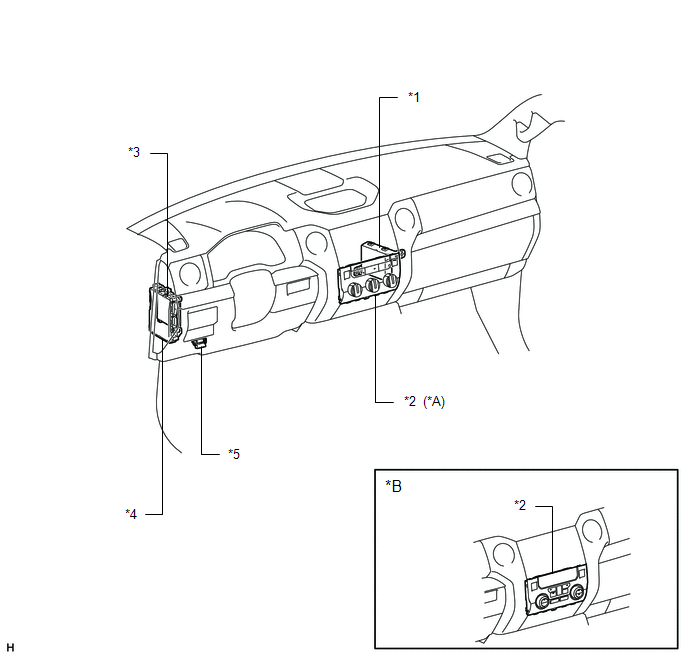
|
Toyota Tundra Owners Manual > Multimedia: Bluetooth
Bluetooth ■When using the Bluetooth audio system In the following conditions, the system may not function. If the portable audio player is turned off If the portable audio player is not connected If the portable audio player's battery is low There may be a delay if a cellular phone connection is m ...


