Toyota Tundra Service Manual: Terminals Of Ecu

TERMINALS OF ECU

*A

Main Body ECU (Multiplex Network Body ECU) with 1 connector

-

-

*1

Main Body ECU (Multiplex Network Body ECU)

-

-

*A

Main Body ECU (Multiplex Network Body ECU) with 3 connectors

-

-

*1

Main Body ECU (Multiplex Network Body ECU)

-

-

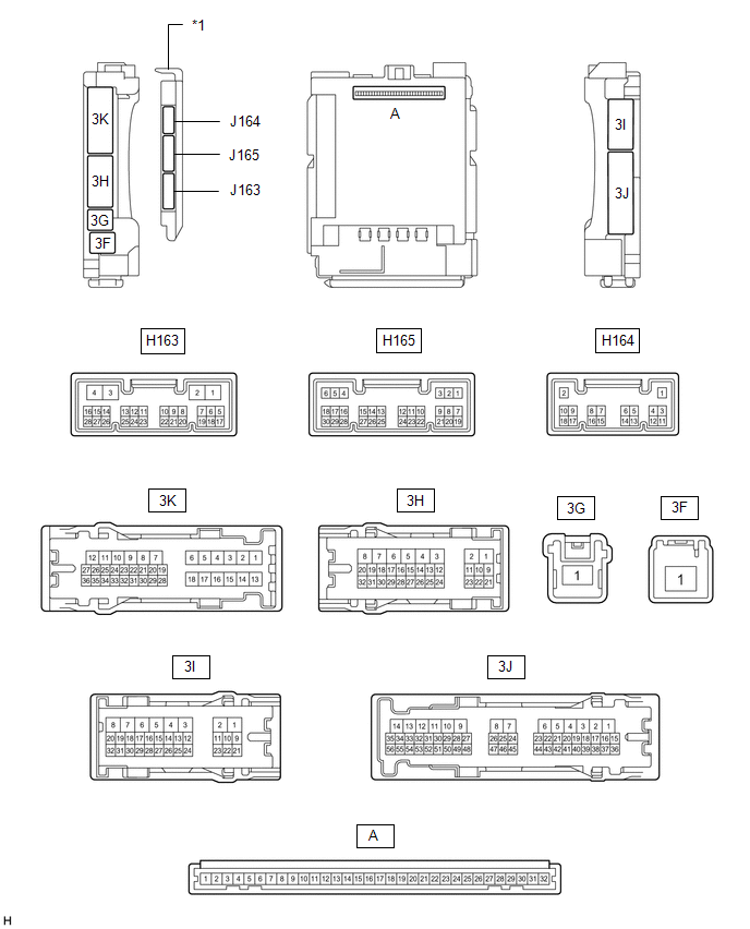
1. CHECK DRIVER SIDE JUNCTION BLOCK ASSEMBLY AND MAIN BODY ECU (MULTIPLEX NETWORK BODY ECU)

(a) Remove the main body ECU (multiplex network body ECU) from the driver side junction block assembly.

Click here

(b) Connect the driver side junction block assembly connectors.

(c) Measure the voltage and resistance according to the value(s) in the table below.

Terminal No. (Symbol)

Wiring Color

Terminal Description

Condition

Specified Condition

A-32 (IG) - Body ground

None - Body ground

Ignition power supply

Ignition switch ON

11 to 14 V

Ignition switch off

Below 1 V

A-31 (BECU) - Body ground

None - Body ground

Battery power supply

Always

11 to 14 V

A-30 (ACC) - Body ground

None - Body ground

ACC power supply

Ignition switch ACC

11 to 14 V

Ignition switch off

Below 1 V

A-11 (GND1) - Body ground

None - Body ground

Ground

Always

Below 1 Ω

(d) Install the main body ECU (multiplex network body ECU) to the driver side junction block assembly.

Click here

(e) Measure the pulse according to the value(s) in the table below.

Terminal No. (Symbol)

Wiring Color

Terminal Description

Condition

Specified Condition

A-16 (LIN2) - Body ground

None - Body ground

LIN communication line

Ignition switch ON

Pulse generation

2. CHECK POWER WINDOW REGULATOR MASTER SWITCH ASSEMBLY (for Power Window Control System [w/ Jam Protection Function])

(a) Disconnect the N2 power window regulator master switch assembly connector.

(b) Measure the voltage and resistance according to the value(s) in the table below.

Terminal No. (Symbols)

Wiring Color

Terminal Description

Condition

Specified Condition

N2-3 (B) - N2-1 (E)

R - W-B

Battery power supply

Always

11 to 14 V

N2-1 (E) - Body ground

W-B - Body ground

Ground

Always

Below 1 Ω

3. CHECK FRONT POWER WINDOW REGULATOR MOTOR ASSEMBLY LH (for Power Window Control System [w/ Jam Protection Function])

(a) Disconnect the N12 front power window regulator motor assembly LH connector.

(b) Measure the voltage and resistance according to the value(s) in the table below.

Terminal No. (Symbols)

Wiring Color

Terminal Description

Condition

Specified Condition

N12-2 (B) - N12-1 (GND)

P - W-B

Battery power supply

Always

11 to 14 V

N12-1 (GND) - Body ground

W-B - Body ground

Ground

Always

Below 1 Ω

4. CHECK FRONT POWER WINDOW REGULATOR MOTOR ASSEMBLY RH (for Power Window Control System [w/ Jam Protection Function])

(a) Disconnect the M11 front power window regulator motor assembly RH connector.

(b) Measure the voltage and resistance according to the value(s) in the table below.

Terminal No. (Symbols)

Wiring Color

Terminal Description

Condition

Specified Condition

M11-2 (B) - M11-1 (GND)

V - W-B

Battery power supply

Always

11 to 14 V

M11-1 (GND) - Body ground

W-B - Body ground

Ground

Always

Below 1 Ω

5. CHECK SLIDING ROOF DRIVE GEAR SUB-ASSEMBLY (SLIDING ROOF ECU) (w/ Sliding Roof System)

(a) Disconnect the W3 sliding roof drive gear sub-assembly connector.

(b) Measure the voltage and resistance according to the value(s) in the table below.

Terminal No. (Symbols)

Wiring Color

Terminal Description

Condition

Specified Condition

W3-9 (IG) - Body ground

SB - Body ground

IG power supply

Ignition switch ON

11 to 14 V

Ignition switch off

Below 1 V

W3-10 (B) - Body ground

L - Body ground

+B power supply

Always

11 to 14 V

W3-8 (E) - Body ground

W-B - Body ground

Ground

Always

Below 1 Ω

6. CHECK AIR CONDITIONING AMPLIFIER ASSEMBLY

(a) Measure the voltage and resistance according to the value(s) in the table below.

HINT:

Check from the rear of the connector while it is connected to the air conditioning amplifier.

Terminal No. (Symbols)

Wiring Color

Terminal Description

Condition

Specified Condition

J19-1 (IG+) - J19-14 (GND)

B - W-B

Ignition power supply

Ignition switch ON

11 to 14 V

Ignition switch off

Below 1 V

J19-21 (B) - J19-14 (GND)

GR - W-B

Battery power source

Always

11 to 14 V

J19-14 (GND) - Body ground

W-B - Body ground

Ground

Always

Below 1 Ω

7. CHECK AIR CONDITIONING CONTROL ASSEMBLY

(a) Disconnect the J127 air conditioning control assembly connector.

(b) Measure the voltage and resistance according to the value(s) in the table below.

Terminal No. (Symbols)

Wiring Color

Terminal Description

Condition

Specified Condition

J127-4 (IG+) - J127-5 (GND)

Y - W-B

Ignition power supply

Ignition switch ON

11 to 14 V

Ignition switch off

Below 1 V

J127-5 (GND) - Body ground

W-B - Body ground

Ground

Always

Below 1 Ω

    System Diagram

    Power Distribution

    See More:

    Toyota Tundra Service Manual > Sliding Roof System: Dtc Check / Clear
    DTC CHECK / CLEAR 1. CHECK DTC (a) Connect the Techstream to the DLC3. (b) Turn the ignition switch ON. (c) Turn the Techstream on. (d) Enter the following menus: Select: Body Electrical / Sliding Roof / Trouble Codes. (e) Check the DTCs. 2. CLEAR DTC (a) Connect the Techstream to the DLC3. (b) Turn ...

    Toyota Tundra Owners Manual

    Toyota Tundra Service Manual

    © 2024 Copyright www.ttundra.com
    0.0117